Bracelet forming and manufacturing device

A technology for making devices and bracelets, which can be applied to bracelets, feeding devices, positioning devices, etc., can solve the problems of time-consuming, labor-intensive, low-efficiency, etc.

Active Publication Date: 2020-10-30
永康市杰力衡器有限公司
View PDF5 Cites 3 Cited by
  • Summary
  • Abstract
  • Description
  • Claims
  • Application Information

AI Technical Summary

Problems solved by technology

[0005] In order to overcome the shortcomings of time-consuming, laborious and inefficient production of bracelets with existing tools, the technical problem to be solved is: to provide a bracelet forming device capable of transmitting metal strips at intervals, bending and forming them, and taking out bracelets

Method used


Image

  • Bracelet forming and manufacturing device
  • Bracelet forming and manufacturing device
  • Bracelet forming and manufacturing device

Examples


Embodiment 1

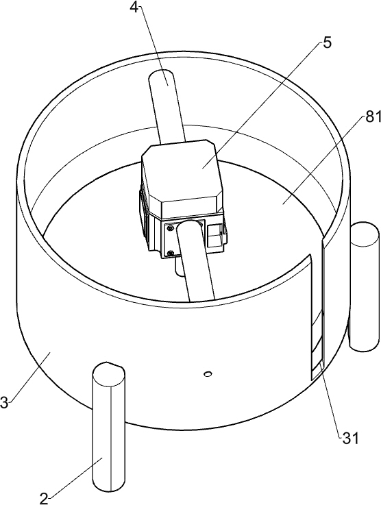
[0061] A bracelet forming device, such as figure 1 with 8 As shown, it includes support table 1, support feet 2, extrusion frame 3, fixed rod 4, motor 5, push mechanism 6, discharge mechanism 7 and forming pressure plate 81, and the left side of the top of support table 1 is evenly connected with three supports An extrusion frame 3 is connected between the foot 2 and the support foot 2, and the right rear side of the extrusion frame 3 is provided with a feed port 31, and a fixed rod 4 is connected between the upper side of the extrusion frame 3, and a motor is connected in the middle of the fixed rod 4 5. The bottom of the output shaft of the motor 5 is connected with a forming pressure plate 81, and the forming pressure plate 81 is connected with the extrusion frame 3 in a rotational manner. The right side of the top of the support table 1 is connected with the push mechanism 6, and the left side of the push mechanism 6 is connected with the motor 5 to support A discharge me...

Embodiment 2

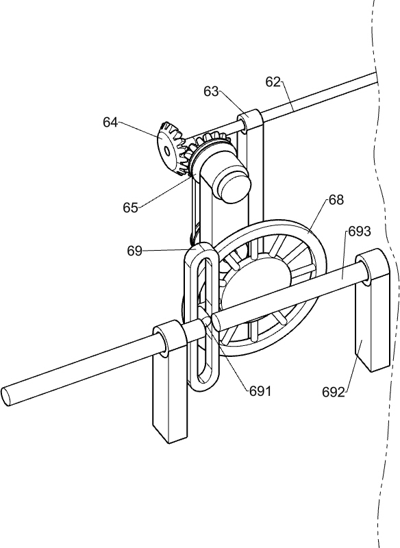
[0064] On the basis of Example 1, such as Figure 2-4 As shown, the push mechanism 6 includes a first bevel gear set 61, a first transmission rod 62, a first support shaft 63, a second bevel gear set 64, a pulley transmission group 65, a biaxial support shaft 66, and a second transmission rod 67 , runner 68, reciprocating sleeve 69, rotating column 691, second support shaft 692 and reciprocating rod 693, three first support shafts 63 are connected at intervals on the right side of the top of the support table 1, and the first support shaft 63 is connected with the discharge mechanism 7 , the first transmission rod 62 is rotatably connected between the first support shafts 63, the left side of the first transmission rod 62 passes through the extrusion frame 3, and the first transmission rod 62 is connected to the output shaft of the motor 5 on the left side. The bevel gear set 61, the right side of the top of the support table 1 is connected with a biaxial support shaft 66, the...

Embodiment 3

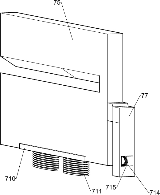
[0067] On the basis of Example 2, such as Figure 4-12 As shown, the discharge mechanism 7 includes a guide frame 71, a discharge frame 74, a grooved baffle 75, a connection block 77, a support block 78, a placement frame 79, a limit block 710, a first spring 711, and an extrusion block 712. , extrusion rod 713 and second spring 714, support table 1 top middle rear side is connected with guide frame 71, guide frame 71 is positioned at the left side of second support shaft 692, guide frame 71 top has first guide groove 73, guide frame There are second through holes 72 on the left and right sides of the upper part of 71, the second through holes 72 communicate with the first guide groove 73, the upper part of the front side of the guide frame 71 is connected with a placement frame 79, and the tops of the two first support shafts 63 on the left side Support blocks 78 are all provided, and a discharge frame 74 is connected between the tops of the support blocks 78, the rear side o...


PUM


Abstract

The invention relates to a manufacturing device, in particular to a bracelet forming and manufacturing device. According to the technical problem to be solved, the bracelet forming and manufacturing device can convey metal bars at intervals, bend and form the metal bars, and take out bracelets. According to the technical scheme, the bracelet forming and manufacturing device comprises a supportingdesk, supporting legs, extruding frames, fixing rods, a motor and a forming pressure disc, wherein the supporting legs are uniformly connected to the left side of the top of the supporting desk, the extruding frames are connected among the supporting legs, a feeding opening is formed in the right rear side of each extruding frame, the fixing rods are connected among the upper sides of the extruding frames, the motor is connected among the fixing rods, the forming pressure disc is connected to the bottom of an output shaft of the motor, and the forming pressure disc is connected with the extruding frames in a rotating manner. By means of cooperation among the motor, a pushing mechanism and a discharging mechanism, the metal bars do not need to be conveyed manually, the effects of falling off the metal bars and pushing the metal bars at the same time can be achieved, time and labor are saved, and efficiency is improved.

Description

technical field [0001] The invention relates to a manufacturing device, in particular to a bracelet molding manufacturing device. Background technique [0002] A bracelet is a ring-shaped ornament worn on the wrist. The role of bracelets generally has three aspects: one is to show identity and highlight personality; the other is to beautify the arm; the third is to protect the body. [0003] When making a bracelet, it is first made into a ring shape and then processed. When most manufacturers make the shape of bracelets, workers usually use cylindrical wooden tools as auxiliary equipment for making bracelets after making metal materials into flat strips, and then place the flat strips of metal materials on top of the wooden tools. At the bottom, iron tools are used to wind it on wooden tools, which requires workers to repeatedly operate before mass production can be seen, which requires a lot of manpower and is not efficient. [0004] Therefore, in order to improve the ef...

Claims


Application Information

Patent Timeline
IPC IPC(8): B21D7/16B21D43/00B21D43/13B21D45/02A44C5/00A44C27/00
CPCB21D45/02B21D7/16B21D43/003B21D43/13A44C27/002A44C5/0092
Inventor 杜仕超
Owner 永康市杰力衡器有限公司
Why Eureka
Try Eureka