Numerical control milling machine tool looseness protection device

A protection device, the technology of CNC milling machine, applied in the direction of milling machine equipment, milling machine equipment details, maintenance and safety accessories, etc., to achieve the effect of protecting life safety, compact structure and not easy to interfere

Inactive Publication Date: 2020-10-30
杭州丽宿塔机械科技有限公司
0 Cites 0 Cited by

AI-Extracted Technical Summary

Problems solved by technology

[0002] CNC milling machines can process parts that ordinary machine tools cannot process or are difficult to process. The degree of production automation is high and the labor intensity of the operator can be reduced. Therefore, it is widely used in modern enterprises. Compared with traditional machine t...

Method used

Working step is: this device is installed on the upper side of CNC milling machine head, makes friction block 11 contact with head wall, rotates hand wheel 21, and hand wheel 21 drives ratchet 19 by rotating shaft 17, and ratchet 19 is locking Under the action of the switch 72, the rotating shaft 17 is driven to rotate in one direction, and the gear 18 drives the rack 13 to move to the left, so that the friction blocks 11 on the left and right sides are pressed against the upper side of the machine head; slide the lifting shaft 33, turn the locking screw 34, and adjust the lifting shaft 33 height, rotate the conical baffle 40, rotate the adjustment screw 39, lock the adjustment rod 76, adjust the rotation angle of the conical baffle 40, make the conical baffle 40 close to the machine head, save the processing space, and avoid contact with the workpiece Interference; turn the spool adjustment wheel 45, the spool adjustment wheel 45 pulls the line 44 through the spool 43, the line 44 drives the measuring body 47 to move to the left, and fine-tunes the distance between the measuring axis 49 and the tool; the machine tool starts, the main shaft starts to rotate, and the measuring mechanism 77 Real-time detection of tool shake, if the...

Abstract

A numerical control milling machine tool looseness protection device comprises a movable rod. A rack is arranged on the right side of the movable rod. A sliding body is arranged on the right side of the movable rod. A locking mechanism is arranged between the sliding body and the movable rod. A friction block is fixedly arranged on the lower side of the movable rod. The friction block is fixedly arranged on the lower side of the sliding body. An arc-shaped body is fixedly arranged on the right side of the movable rod. The device is installed at the assigned position of a machine tool, the non-acting part of a tool is covered by the device, beating of the tool can be detected by the device, and when accidents happen, the protection device is rapidly started, the tool which is out of controlis prevented from flying out, and life safety of operators is protected; the device is high in adaptability and can be installed on most of numerical control milling machines; and the device is compact in tail end structure, is not likely to generate interference and does not occupy much machining space.

Application Domain

Technology Topic

Image

  • Numerical control milling machine tool looseness protection device
  • Numerical control milling machine tool looseness protection device
  • Numerical control milling machine tool looseness protection device

Examples

  • Experimental program(1)

Example Embodiment

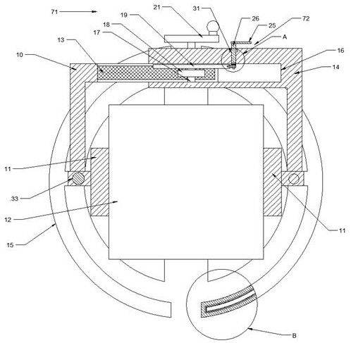
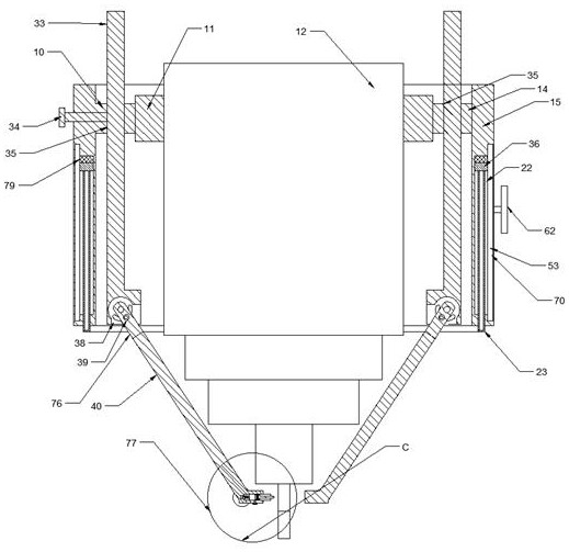
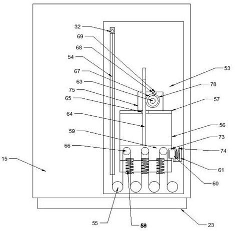
[0017] Combine below Figure 1-6 For the convenience of description, the orientations mentioned below are now specified as follows: figure 1 The projection relationship of itself is the same as the up, down, left, right, front, and rear directions.
[0018] A numerical control milling machine tool loosening protection device described in conjunction with accompanying drawings 1-6 includes a movable rod 10, a gear rack 13 is provided on the right side of the movable rod 10, and a sliding body 14 is provided on the right side of the movable rod 10, so A locking mechanism 71 is arranged between the sliding body 14 and the movable rod 10 , a friction block 11 is fixedly arranged on the lower side of the movable rod 10 , and the friction block 11 is fixedly arranged on the lower side of the sliding body 14 , so The right side of the movable rod 10 is fixedly provided with an arc-shaped body 15, the right side of the sliding body 14 is fixedly provided with an arc-shaped body 15, and the rear side of the arc-shaped body 15 is provided with a pop-up cavity 22, and the pop-up cavity 22 slides inside. A pop-up slider 36 is provided, a reset magnet 79 is fixed on the upper side wall of the pop-up cavity 22, a blocking body 23 is fixed on the rear side of the pop-up slide block 36, and a blocking cavity 24 is provided in the blocking body 23. The blocking cavity 24 is provided with a non-Newtonian fluid, the outside of the ejection cavity 22 is provided with an acceleration chamber 53, and an acceleration mechanism 70 is arranged in the acceleration chamber 53, and the acceleration mechanism 70 drives the ejection slider 36 to rapidly move toward the ejection block 36. Moving downward, the acceleration mechanism 70 includes a fixed wheel 55 on the lower side of the acceleration chamber 53 , the ejection slider 36 is located in the acceleration chamber 53 and is fixed with an ejection shaft 32 , and the ejection shaft 32 is fixedly arranged. There is an acceleration line 54, the acceleration chamber 53 is provided with an ejection cavity 56, and an ejection block 59 is slid in the ejection cavity 56, and a moving wheel 66 is arranged on the ejection block 59. The ejection block 59 and the ejection cavity An ejection spring 58 is arranged between the lower side walls of 56, an acceleration slot 73 is arranged on the right side of the ejection block 59, an acceleration switch slot 74 is arranged in the right side wall of the ejection cavity 56, and the acceleration switch slot 74 is in the An ejection stopper 60 is slidably provided, and an ejection electromagnet 61 is fixed on the right side of the acceleration switch slot 74 . A spring is arranged between the ejection electromagnet 61 and the ejection stopper 60 , and the ejection stopper 60 is locked. In the acceleration slot 73 , a reset linkage rod 64 is fixed on the upper side of the ejection block 59 , a reset cavity 75 is provided on the inner side of the acceleration chamber 53 on the upper side of the ejection cavity 56 , and a reset cavity 75 is provided on the inner side of the reset cavity 75 . There is a reset lever 63, the reset lever 63 is fixedly provided with a ratchet wheel 67, the reset lever 63 is located at the rear side of the ratchet wheel 67 and is fixedly provided with a reset gear 78, and the reset gear 78 meshes with the reset linkage rod 64, the The upper side wall of the reset cavity 75 is fixedly provided with a ratchet pawl 68, the reset cavity 75 is located on the right side of the ratchet pawl 68 with a ratchet magnet 69, and the reset cavity 75 communicates with the ejection cavity 56. Empty hole 65 , the reset linkage rod 64 passes through the empty hole 65 , the upper side wall of the ejection cavity 56 is fixedly provided with a buffer pad 57 , and the acceleration line 54 passes through the fixed wheel 55 and the moving wheel 66 , the acceleration line 54 is fixed on the fixed wheel 55 at the end, the reset hand wheel 62 is fixed on the outside of the reset cavity 75, the lifting hole 35 is provided on the left side of the movable rod 10, and the right side of the sliding body 14 is provided There is a lifting hole 35, a lifting shaft 33 is slidably arranged in the lifting hole 35, and a locking screw 34 is threadedly connected to the right side of the movable rod 10, so The end of the locking screw 34 is in contact with the lifting shaft 33 . The rear end of the lifting shaft 33 is provided with an adjustment cavity 38 , and an adjustment rod 76 is rotated in the adjustment cavity 38 . Adjusting the screw 39, the lower side of the adjusting rod 76 is fixedly provided with a conical baffle 40, and the bottom of the conical baffle 40 is provided with a measuring mechanism 77, and the measuring mechanism 77 can be used to run the material tool.
[0019] Advantageously, the locking mechanism 71 includes a sliding cavity 16 provided on the sliding body 14 , the sliding cavity 16 rotates up and down and is provided with a rotating shaft 17 , and the rotating shaft 17 is located in the sliding cavity 16 and is fixedly provided with a gear 18 , the gear 18 meshes with the rack 13 , the rotating shaft 17 is located on the upper side of the gear 18 and is fixedly provided with a ratchet 19 , the sliding cavity 16 is located on the right side of the gear 18 and the upper side wall is provided with a locking The switch 72, the locking switch 72 can make the ratchet wheel 19 rotate in one direction, the sliding cavity 16 is located on the upper side wall of the ratchet wheel 19 and has a hole, and the rotating shaft 17 passes through the hole of the sliding cavity 16, A hand wheel 21 is fixed on the upper end of the rotating shaft 17 .
[0020] Beneficially, the locking switch 72 includes a switch cavity 31 provided on the upper side wall of the sliding cavity 16 , and a switch shaft 26 is rotatably disposed in the switch cavity 31 , and the switch shaft 26 extends to the sliding body 14 A switch lever 25 is fixed on the upper end surface, the lower end surface of the switch shaft 26 extends into the sliding cavity 16, a rotating shaft 27 is fixed on the lower end surface of the switch shaft 26, and a ratchet pawl 28 is fixed on the rotating shaft 27. A ratchet torsion spring 29 is provided between the ratchet pawl 28 and the upper side wall of the switch shaft 26 , and the ratchet pawl 28 is engaged with the ratchet wheel 19 .
[0021]Beneficially, the measuring mechanism 77 includes a length adjusting chamber 46 provided on the lower side of the tapered baffle 40 , and a measuring body 47 is slidably provided in the length adjusting chamber 46 , and the measuring body 47 is connected to the length adjusting chamber 46 . A wire 44 is arranged between the chambers 46 , a spool 43 is arranged on the left side of the length adjustment chamber 46 , a wire 44 is connected between the spool 43 and the measuring body 47 , and a spool adjustment is fixed on the rear side of the spool 43 Wheel 45, the tapered baffle 40 is located on the lower side of the measuring body 47 and is provided with a measuring locking pin 51, the measuring body 47 is provided with an induction cavity 50, and the sensing cavity 50 is slidably provided with a measuring shaft 49, so An induction switch 52 is fixed on the left side of the induction cavity 50 , a spring is arranged between the induction switch 52 and the measurement shaft 49 , and the measurement shaft 49 extends a certain distance from the right side.
[0022] The working steps are: install the device on the upper side of the CNC milling machine head, make the friction block 11 contact the head wall, rotate the handwheel 21, the handwheel 21 drives the ratchet 19 through the rotating shaft 17, and the ratchet 19 is in the lock switch 72. Under the action, the rotating shaft 17 is driven to rotate in one direction, and the gear 18 drives the rack 13 to move to the left, so that the friction blocks 11 on the left and right sides press the upper side of the machine head; slide the lifting shaft 33 and turn the locking screw 34 to adjust the height of the lifting shaft 33 , rotate the conical baffle 40, turn the adjustment screw 39, lock the adjustment rod 76, adjust the rotation angle of the conical baffle 40, make the conical baffle 40 close to the machine head, save the processing space, and avoid interference with the workpiece; turn Spool adjustment wheel 45, spool adjustment wheel 45 pulls wire 44 through spool 43, wire 44 drives measuring body 47 to move to the left, and fine-tunes the distance between measuring shaft 49 and the tool; the machine tool is started, the spindle starts to rotate, and the measuring mechanism 77 detects the tool in real time If the tool vibrates abnormally, the measuring shaft 49 is compressed, the sensing switch 52 is triggered by the measuring shaft 49, the sensing switch 52 controls the ratchet magnet 69 to attract the ratchet pawl 68 from the ratchet 67, and the reset linkage rod 64 can move up and down freely. , the induction switch 52 controls the ejection electromagnet 61 to turn on, the ejection electromagnet 61 attracts the ejection block 60 to retreat, the ejection spring 58 pushes the ejection block 59 to move upward, and the ejection block 59 drives the ejection shaft through the moving wheel 66 , the fixed wheel 55 and the acceleration line 54 32 moves down rapidly, and the ejection shaft 32 pushes the blocking body 23 to wrap around the tool to prevent the tool from popping out; when resetting, the ratchet magnet 69 is closed, the ratchet pawl 68 is engaged with the ratchet 67, and the reset handwheel 62 is rotated, and the reset handwheel 62 drives the reset The linkage rod 64 moves downward in one direction, the reset linkage rod 64 compresses the ejection block 59 and moves downward, manually pushes the blocking body 23 to reset to the initial position, the reset magnet 79 attracts the ejection slider 36, and the reset is completed.
[0023] The above-mentioned embodiments are only intended to illustrate the technical concept and characteristics of the present invention, and the purpose thereof is to enable those skilled in the art to understand the content of the present invention and implement it, but not to limit the protection scope of the present invention. All equivalent changes or modifications made according to the spirit of the present invention should be covered within the protection scope of the present invention.

PUM

no PUM

Description & Claims & Application Information

We can also present the details of the Description, Claims and Application information to help users get a comprehensive understanding of the technical details of the patent, such as background art, summary of invention, brief description of drawings, description of embodiments, and other original content. On the other hand, users can also determine the specific scope of protection of the technology through the list of claims; as well as understand the changes in the life cycle of the technology with the presentation of the patent timeline. Login to view more.

Similar technology patents

High-strength waterproof rock wool board preparation system

PendingCN114543506AReduce labor burdenProtect life safetyVertical furnacesIncrustation removal devicesSlagWool
Owner:王子蔚

Classification and recommendation of technical efficacy words

  • Adaptable
  • Protect life safety

Application interface rendering method and apparatus

ActiveCN105354013AAdaptableAvoid various pitfallsSpecific program execution arrangementsInformation mappingComputer graphics (images)
Owner:ALIBABA GRP HLDG LTD

Dynamic thermal protection performance testing and evaluating device

InactiveCN104316562AProtect life safetyMaterial heat developmentHeat flux sensorHeat flow
Owner:ZHANGJIAGANG INST OF IND TECH SOOCHOW UNIV
Why Eureka
Try Eureka