Welding wire speed regulation control system

A control system and speed regulation technology, applied in the direction of manufacturing tools, welding equipment, welding accessories, etc., can solve the problems of insufficient technical solutions, affecting the welding effect, and not considering the actual transmission status of welding wire, etc.

Inactive Publication Date: 2020-10-30
TONGLING TONGFEI TECH
View PDF0 Cites 1 Cited by
  • Summary
  • Abstract
  • Description
  • Claims
  • Application Information

AI Technical Summary

Problems solved by technology

[0002] In the welding operation of the manipulator, when changing the type of welding wire, the welding wire in the welding wire guide of the manipulator needs to be withdrawn to the wire reel, which often causes the welding wire on the welding wire reel to be entangled, causing the chaotic winding of the welding wire to change the wire feeding time when it is used again. The stable rate, which in turn affects the effect of wire welding
[0003] The existing welding wire speed control system generally provides parameter setting through the control part, and the driving part performs wire feeding drive under the control of the control part. The motor drives the driving wheel to rotate to provide power for wire feeding, and the driven wheel presses the welding wire into the wire feeding groove on the wire feeding wheel, increasing the friction between the welding wire and the wire feeding wheel, so that the welding wire can be sent out smoothly; Part of it is difficult to retract the welding wire on the wire reel in a regular manner, which makes it difficult to control the speed of the chaotically wound welding wire on the wire reel during

Method used


Image

  • Welding wire speed regulation control system
  • Welding wire speed regulation control system
  • Welding wire speed regulation control system

Examples


Embodiment approach

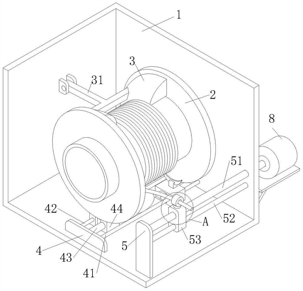
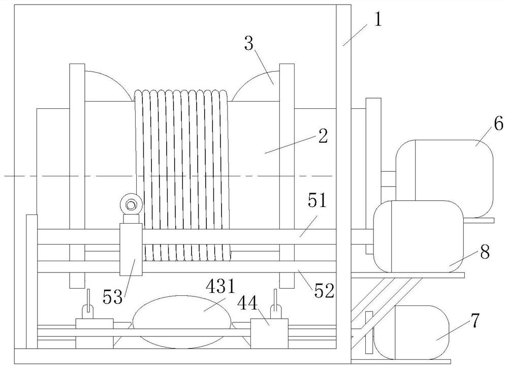
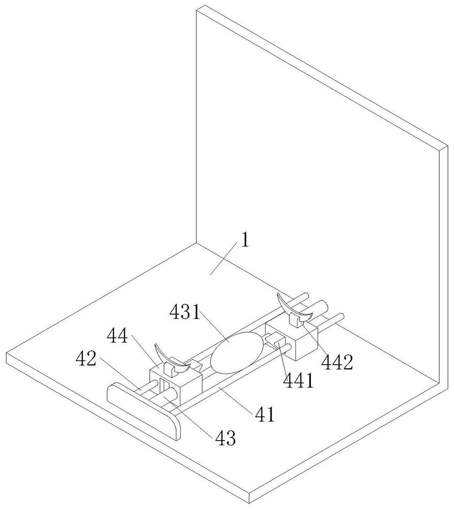
[0025] As an embodiment of the present invention, a No. 1 limit assembly 4 is provided on the bottom surface of the frame 1 below the wire reel 2, and the No. 1 limit assembly 4 includes a No. 1 lead screw 41, a No. 2 lead screw 42, No. 1 slide bar 43, support block 44 and No. 2 motor 7; the axial direction of described No. 1 leading screw 41, No. 2 leading screw 42 and No. 1 slide bar 43 is parallel to the axial direction of welding wire reel 2, and the axial direction of described No. 1 Leading screw 41 and No. 2 leading screw 42 are symmetrically distributed on the both sides of No. 1 slide bar 43; Described support block 44 is two, two support blocks are positioned at the two ends of No. 1 slide bar 43, one side of support block 44 Slidingly connected on the No. 1 slide bar 43, the other side is connected with the No. 1 lead screw 41 and the No. 2 lead screw 42 respectively. The controller controls the No. 2 motor 7 to drive the No. 1 lead screw 41 to rotate, and the No. 2 ...


PUM


Abstract

The invention relates to the technical field of welding equipment, and particularly relates to a welding wire speed regulation control system. The welding wire speed regulation control system comprises a rack, a wire reel, a guide block, a driving motor and a controller; the guide block is positioned at the upper part of the wire reel; a supporting block is arranged below the wire reel; a guide block is arranged on a path for withdrawing the welding wire to the wire reel; and the guide block, the supporting block, the guide block and lead screw pairs of the guide block, the supporting block and the guide block form a welding wire control system together with the driving motor and the controller. When the wire reel rotates to take back the welding wire, the welding wire is wound on the wirereel in a disordered manner, so that the wire feeding rate of the welding wire during reuse is influenced; therefore, through cooperation of the guide block, the supporting block and the guide blockwhich are arranged on the rack, the winding area, the winding strength and the initial winding angle of the welding wire during wire winding are limited, the problem that the welding wire is wound disorderly during wire winding of the wire reel is solved, and the conveying rate of the welding wire in subsequent use is stabilized.

Description

technical field [0001] The invention relates to the technical field of welding equipment, in particular to a welding wire speed regulation control system. Background technique [0002] In the welding operation of the manipulator, when changing the type of welding wire, the welding wire in the welding wire guide of the manipulator needs to be withdrawn to the wire reel, which often causes the welding wire on the welding wire reel to be entangled, causing the chaotic winding of the welding wire to change the wire feeding time when it is used again. The stable rate, which in turn affects the effect of wire welding. [0003] The existing welding wire speed control system generally provides parameter setting through the control part, and the driving part performs wire feeding drive under the control of the control part. The motor drives the driving wheel to rotate to provide power for wire feeding, and the driven wheel presses the welding wire into the wire feeding groove on the...

Claims


Application Information

Patent Timeline
IPC IPC(8): B23K9/133B23K9/32
CPCB23K9/133B23K9/32
Inventor 曹骏骅徐湘华陈振伟
Owner TONGLING TONGFEI TECH
Why Eureka
Try Eureka