Damping spring grouping assembling device for clutch damping spring assembling machine

A technology for damping springs and assembling devices, which is applied to devices for coating liquid on surfaces, sorting, metal processing, etc., can solve the problems of affecting measurement results and low measurement accuracy of measurement equipment, and achieves uniform coating effect and fast measurement. , grouping accurate effects

Active Publication Date: 2020-10-30
ZHEJIANG QIDIE AUTOMOBILE PARTS CO LTD
View PDF6 Cites 3 Cited by
  • Summary
  • Abstract
  • Description
  • Claims
  • Application Information

AI Technical Summary

Problems solved by technology

[0006] In view of the above problems, the present invention provides a shock absorbing spring group assembly device for a clutch shock absorbing spring assembly machine, in which the shock absorbing springs are compressed in parallel in the compression measuring mechanism, and the length of the shock absorbing springs after compression is measured to measure the length of the shock absorbing springs. In the process of sieving and grouping the compressed length, the shock absorbing spring is positioned at the center directly below the compression measuring mechanism by using the contraction of the centering rod in the centering mechanism, and the shock absorbing spring is adjusted by the compression measuring mechanism. In the process of compression measurement, it is ensured that the compression of the shock-absorbing spring will not cause inclination, bending, and the situation that affects the measurement results, and solve the technical problem of low measurement accuracy of existing measurement equipment

Method used


Image

  • Damping spring grouping assembling device for clutch damping spring assembling machine
  • Damping spring grouping assembling device for clutch damping spring assembling machine
  • Damping spring grouping assembling device for clutch damping spring assembling machine

Examples


Embodiment

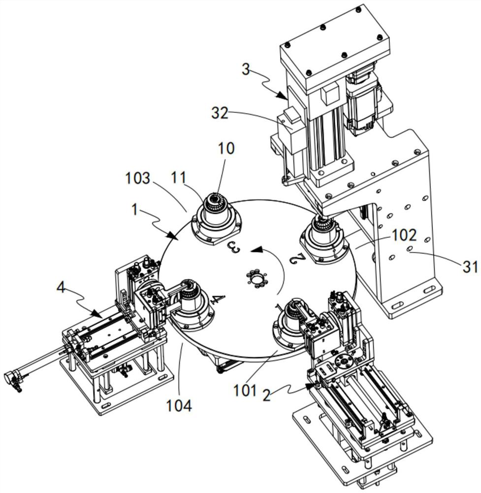
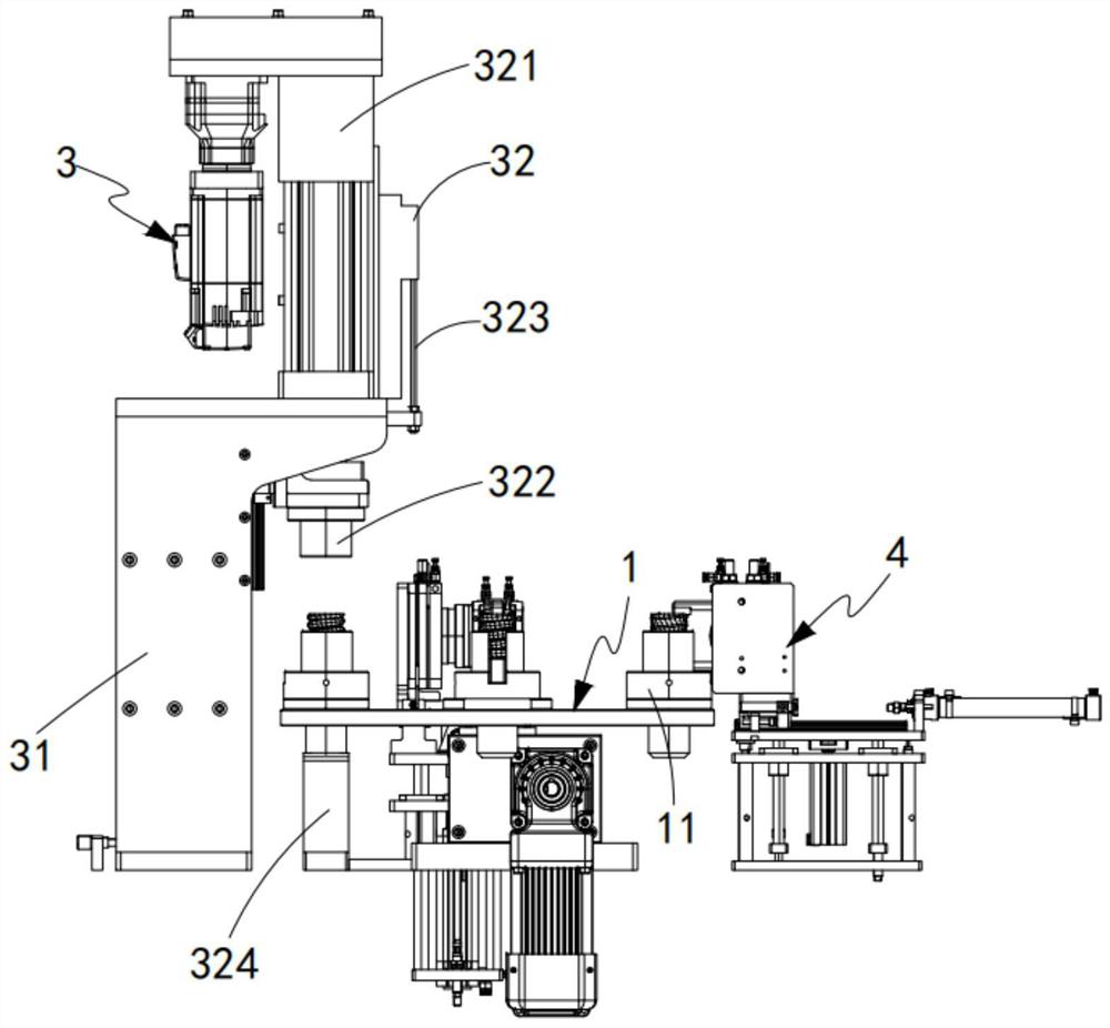
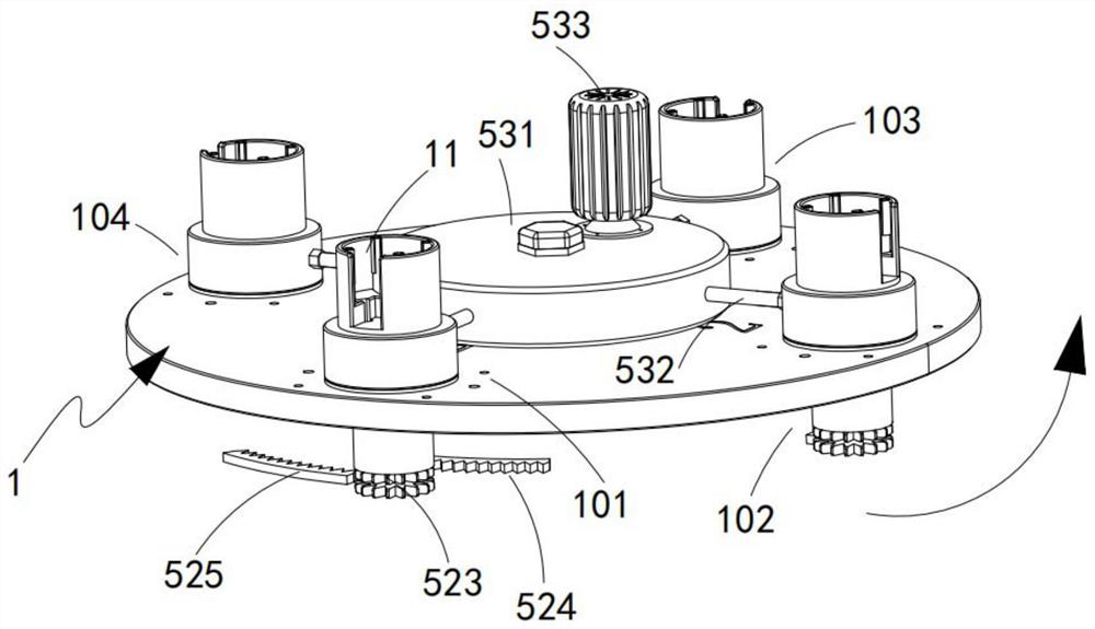
[0073] Such as Figure 1 to Figure 9 As shown, a shock absorbing spring group assembly device for a clutch shock absorbing spring assembly machine includes a turntable 1, and a plurality of positioning mechanisms 11 are equidistantly distributed on the circumference of the turntable 1, and the positioning mechanism 11 is provided with load-absorbing In the cavity 12 of the shock spring 10, a feeding station 101, a compression detection station 102, a transfer station 103, and a discharge station 104 are arranged equidistantly in the direction of rotation of the turntable 1, and also includes:

[0074] Feeding mechanism 2, said feeding mechanism 2 is installed adjacent to said turntable 1, it is located at said loading station 101, and it is used to clamp said shock absorbing spring 10 and place it vertically in said space Inside chamber 12;

[0075] A compression measurement mechanism 3, the compression measurement mechanism 3 is installed adjacent to the turntable 1, and it ...


PUM


Abstract

The invention relates to the technical field of screening machinery for assembling springs on a clutch, in particular to a damping spring grouping assembling device for a clutch damping spring assembling machine. The damping spring grouping assembling device for the clutch damping spring assembling machine comprises a turntable, a feeding mechanism, a compression measuring mechanism, a dischargingmechanism, a centering mechanism and positioning mechanisms distributed on the turntable, wherein the centering mechanism is also installed on the turntable and comprises a plurality of centering rods which are equidistantly arranged along the circumferences of the center lines of cavities inside the positioning mechanisms; the compression measuring mechanism compresses damping springs and measures the length of the compressed damping springs; in the process of screening and grouping according to the compressed length of the damping springs, the damping springs are positioned at the central position right below the compression measuring mechanism by utilizing the contraction of the centering rods in the centering mechanism; and in the process of compression measurement on the damping springs by the compression measuring mechanism, it is ensured that the damping springs do not incline or bend when compressed, and a situation affecting the measurement result does not occur.

Description

technical field [0001] The invention relates to the technical field of screening machinery for assembling springs on clutches, in particular to a damping spring group assembly device for a clutch damping spring assembly machine. Background technique [0002] Clutches are common components in mechanical transmissions that can disengage or engage the transmission system at any time. During the engagement process, the clutch pedal is gradually released, and the pressure plate moves forward under the action of the compression spring, firstly to eliminate the separation gap, and to act on the pressure plate, driven disc and flywheel with sufficient pressing force on the working surface, and then The release bearing moves backwards under the action of the return spring, creating free play and the clutch engages. [0003] When the relevant springs on the clutch, especially the damping springs, are specially matched, since the processing tolerance between the finished springs is gr...

Claims


Application Information

Patent Timeline
Patent Type & Authority Applications(China)
IPC IPC(8): B23P19/04B05C1/02B05C13/02B07C5/02B07C5/08B07C5/36
CPCB05C1/02B05C13/02B07C5/02B07C5/08B07C5/362B23P19/001B23P19/048
Inventor 张勇
Owner ZHEJIANG QIDIE AUTOMOBILE PARTS CO LTD
Why Eureka
Try Eureka