Combined feeding type numerical control lathe

A CNC lathe and composite technology, applied in the field of lathes, can solve the problems of damaged and scrapped parts, increased surface temperature of tools, and unusable tools.

Inactive Publication Date: 2020-10-30
广州优易机械科技有限公司
View PDF10 Cites 2 Cited by
  • Summary
  • Abstract
  • Description
  • Claims
  • Application Information

AI Technical Summary

Problems solved by technology

[0003] In order to solve the melting of the aluminum alloy material in the above technology, the melted aluminum alloy is bonded to the outer side of the tool, causing the outer side of the tool to be passivated and unable to continue to be used, and the temperature of the tool surf

Method used


Image

  • Combined feeding type numerical control lathe
  • Combined feeding type numerical control lathe
  • Combined feeding type numerical control lathe

Examples


Embodiment 1

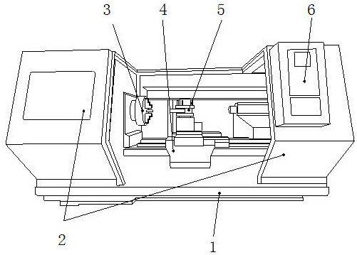
[0024] as attached figure 1 to attach Figure 5 Shown:

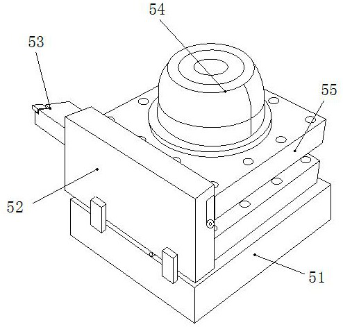
[0025] The invention provides a compound type CNC lathe, the structure of which includes a base 1, a movable door 2, a main shaft 3, a sliding seat 4, a tool rest 5, and a control box 6, and the upper end of the base 1 is movable with the lower end of the movable door 2. Together, the main shaft 3 is connected to the middle part of the left end of the base 1, the sliding seat 4 is slidably connected to the upper side of the middle part of the base 1, the tool holder 5 is connected to the upper end of the sliding seat 4 with bolts, and the control box 6 is connected to the outer side of the movable door 2. Welding connection, the tool holder 5 includes a bottom block 51, a clearing device 52, a cutter 53, a motor 54, and a clip 55, the bottom block 51 is connected with the upper end of the slide seat 4 by bolts, and the cleaning device 52 slides with the outside of the cutter 53 Connected, the cutter 53 is connected wit...

Embodiment 2

[0032] as attached Figure 6 to attach Figure 7 Shown:

[0033] Wherein, the scraper block c6 includes a support frame c61, a central axis c62, a scraper c63, and a limiting plate c64, the support frame c61 is connected to the inner shaft at the right end of the second scraper plate c5, and the central axis c62 is connected to the support frame c61 The outer side of the front is welded and connected, the scraper c63 is riveted to the right end of the support frame c61, the restricting plate c64 is axially connected to the middle of the support frame c61, the restricting plate c64 is installed obliquely, and the installation position is higher than that of the scraper c63, The limiting plate c64 can remove the molten aluminum alloy scraped off by the scraper c63, which is beneficial to improve the cleaning efficiency of the scraper c63 on the surface of the cutter 53.

[0034] Wherein, the limiting plate c64 includes a catch piece r1, a fixed shaft r2, and a contact block r3...


PUM


Abstract

The invention discloses a combined feeding type numerical control lathe. The combined feeding type numerical control lathe structurally comprises a base, a movable door, a spindle, a sliding seat, a tool rest and a control box, wherein the upper end of the base is movably clamped to the lower end of the movable door. A sliding block moves left and right, a jacking block jacks a warping plate through a spring to scrape off aluminum alloy melt cleaned off by the sliding block for storage, a scraping block cleans away the aluminum alloy melt, and the situation that aluminum alloy adheres to the outer side of a tool and makes the outer side of the tool blunt and consequently the tool cannot be used any longer is prevented. A middle shaft on the front side of a supporting frame can connect thescraping block, then, a scraper is cleaned through a limiting plate, a capturing sheet can stick the removed aluminum alloy melt on the limiting plate, a contact block can press the capturing sheet downwards under the supporting of a fixing shaft after the sliding block moves rightwards, then, the warping plate can perform scraping and collecting on the capturing sheet, and the situation that thealuminum alloy melt adheres to the tool and consequently the tool cannot be used any longer or even a machined part is damaged and scraped is prevented.

Description

technical field [0001] The invention belongs to the field of lathes, and more specifically, relates to a compound type CNC lathe. Background technique [0002] The knife-feeding CNC lathe is a compound knife-feeding CNC lathe among the types of CNC lathes. It has the advantages of automatic processing, fast processing speed, and complex parts are processed and formed at one time. There are five knives on the knife-feeding CNC lathe to achieve Grooving, chamfering, cutting, tapping, die, cutting, hole turning and other processes, but in the process of turning the aluminum alloy material with a knife-feeding CNC lathe, the strength of the aluminum alloy will decrease at high temperature, When the speed of the rotating shaft is not increased, the tool holder is controlled to turn the workpiece, or the tool holder does not leave the surface of the workpiece quickly after turning, which will cause the aluminum alloy to melt and cause the melted aluminum alloy to adhere to the out...

Claims


Application Information

Patent Timeline
IPC IPC(8): B23Q11/00
CPCB23Q11/0042
Inventor 王佩
Owner 广州优易机械科技有限公司
Why Eureka
Try Eureka