Needle inserting worktable for micro needles

A workbench and pin insertion technology, applied in workbenches, manufacturing tools, TVs, etc., can solve problems such as time-consuming and labor-intensive difficulty, low efficiency, and difficulty in eliminating omissions or misplaced points.

Pending Publication Date: 2020-10-30
深圳市恩希电子科技有限公司
View PDF0 Cites 0 Cited by
  • Summary
  • Abstract
  • Description
  • Claims
  • Application Information

AI Technical Summary

Problems solved by technology

[0002] The production of high-precision test fixtures is extremely meticulous and demanding, among which microneedle insertion is the most critical and time-consuming and labor-intensive task. The minimum spacing of the layout can reach 0.1mm, because the diameter of the microneedles is small, the density of the pinholes on the jig board is high, and the jig board is multi-layered and there is a gap between each layer of jig boards, and each layer of jig In the case of many factors such as the size of the board and the position of the hole due to the slight deviation caused by processing, it is extremely difficult to complete the pin insertion work through direct observation with the naked eye.
[0003] During the pin insertion process, pin hole misalignment is very easy to occur, resulting in slow insertion speed and low efficiency. Once pin hole misalignment or missing insertion occurs, it is extremely difficult to eliminate missing or misplaced points, and the product rework workload is very large. It greatly affects the efficiency of pin insertion

Method used


Image

  • Needle inserting worktable for micro needles
  • Needle inserting worktable for micro needles
  • Needle inserting worktable for micro needles

Examples


Embodiment Construction

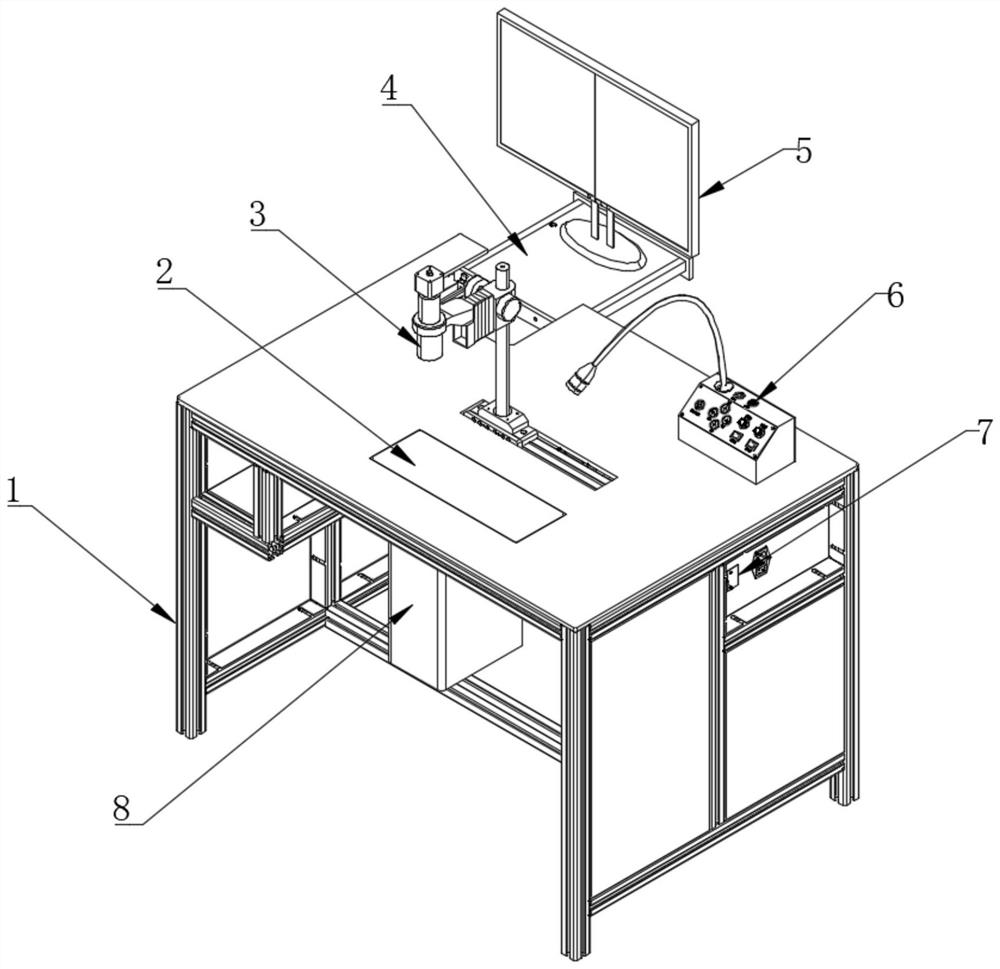
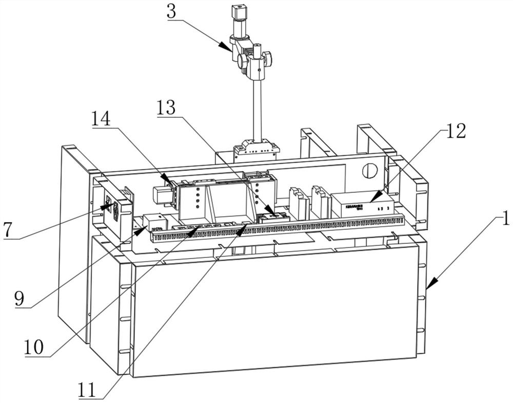
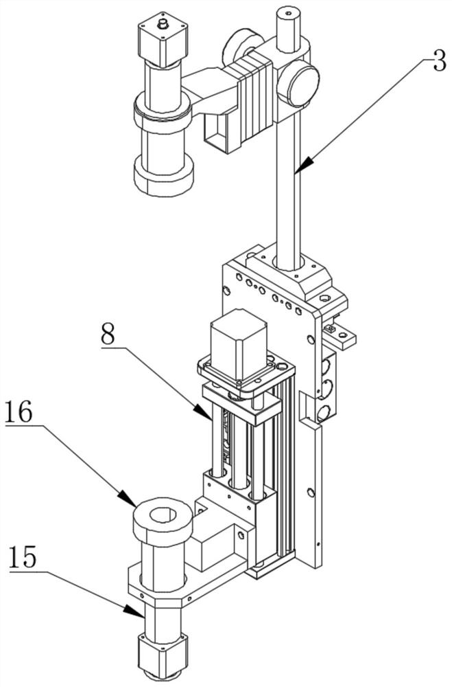
[0025] see Figure 1-8 , in an embodiment of the present invention, a microneedle insertion workbench includes a workbench body 1, a telescopic workbench 4 is slidably connected to the rear side of the upper end of the workbench body 1, and the upper end of the workbench body 1 is far away from the retractable workbench. One side of the table 4 is equipped with a console button centralized control module 6, the middle part of the workbench body 1 is embedded with an upper camera assembly 3, and the upper end of the workbench body 1 is provided with a transparent observation table 2 near the front side of the upper camera assembly 3, One side of the workbench body 1 is embedded with a main power switch 7, the inner side of the workbench body 1 is located at the rear end of the upper camera assembly 3 and a lateral adjustment mechanism 14 is installed, and the inner side of the workbench body 1 is close to the side of the main power switch 7 A 24V power supply 9 is provided, and...


PUM


Abstract

The invention relates to the technical field of high precision testing, and discloses a needle inserting worktable for micro needles. The needle inserting worktable comprises a worktable body, whereina telescopic worktable is slidably connected to the rear side of the upper end of the worktable body, an upper camera assembly is embedded and installed in the middle of the worktable body, a lower camera is fixedly connected to the front end of the inner side of a longitudinal adjusting mechanism, and a display is fixedly connected to the upper end of the telescopic worktable. According to the needle inserting worktable, hole positions of fixture plates which are stacked in multiple layers are subjected to video recording through an upper camera and the lower camera, an operator can intuitively and clearly see the positions of the micro needles and needle holes by observing the display in the process of needle inserting, whether the micro needles are omitted or inserted in wrong positions is timely judged in the process of needle inserting, the injury to eyes caused by excessive use of eyes by the operator is avoided, the efficiency of needle inserting is also greatly improved, the rework rate is greatly reduced, and the worktable can also assist the staff to provide great convenience when inspecting the misplacement or missing insertion points of the needle holes for defective products.

Description

technical field [0001] The invention relates to the technical field of high-precision testing, in particular to a microneedle insertion workbench. Background technique [0002] The production of high-precision test fixtures is extremely meticulous and demanding, among which microneedle insertion is the most critical and time-consuming and labor-intensive task. The minimum spacing of the layout can reach 0.1mm, because the diameter of the microneedles is small, the density of the pinholes on the jig board is high, and the jig board is multi-layered and there is a gap between each layer of jig boards, and each layer of jig In the case of many factors such as the size of the board and the position of the hole due to the slight deviation caused by processing, it is extremely difficult to complete the pin insertion work by direct observation with the naked eye. [0003] During the pin insertion process, pin hole misalignment is very easy to occur, resulting in slow insertion spe...

Claims


Application Information

Patent Timeline
Patent Type & Authority Applications(China)
IPC IPC(8): B25H1/00H04N5/225
CPCB25H1/00H04N23/50H04N23/00
Inventor 刘杰靳燕飞
Owner 深圳市恩希电子科技有限公司
Why Eureka
Try Eureka