Integrated full-sea-depth propeller

A technology of thrusters and shells, which is applied in the field of integrated and integrated full-sea deep thrusters, can solve the problems of higher requirements on materials and processing technology, increased weight and volume of submersibles, increased cost and failure rate, etc. The effect of reduced volume and weight, reduced installation difficulty, and overall weight reduction

Inactive Publication Date: 2020-10-30
CHINA SHIP SCIENTIFIC RESEARCH CENTER (THE 702 INSTITUTE OF CHINA SHIPBUILDING INDUSTRY CORPORATION)
View PDF8 Cites 4 Cited by
  • Summary
  • Abstract
  • Description
  • Claims
  • Application Information

AI Technical Summary

Problems solved by technology

[0003] (1) The driver is installed separately in the pressure tank. The seawater pressure in the deep sea is huge, and a pressure tank with good pressure resistance needs to be processed. The requirements for the material and processing technology of the tank body are relatively high, and the processing is difficult;
[0004] (2) In order to resist the huge seawater pressure, the pressure tank needs to increase the wall thickness of the tank, which increases the weight of the submersible
In order to offset the gravity, a lot of buoyancy materials need to be added, which increases the overall weight and volume of the submersible;
[0005] (3) Electrical signals are transmitted between the driver and the motor through watertight plug-ins and watertight cables, which increases the cost and the incidence of failure;
[0006] (4) The driver and the motor need to be fixed on the carrier through connecting devices, which increases the difficulty of installation on the carrier

Method used


Image

  • Integrated full-sea-depth propeller
  • Integrated full-sea-depth propeller

Examples


Embodiment Construction

[0023] The specific embodiments of the present invention will be further described below in conjunction with the accompanying drawings.

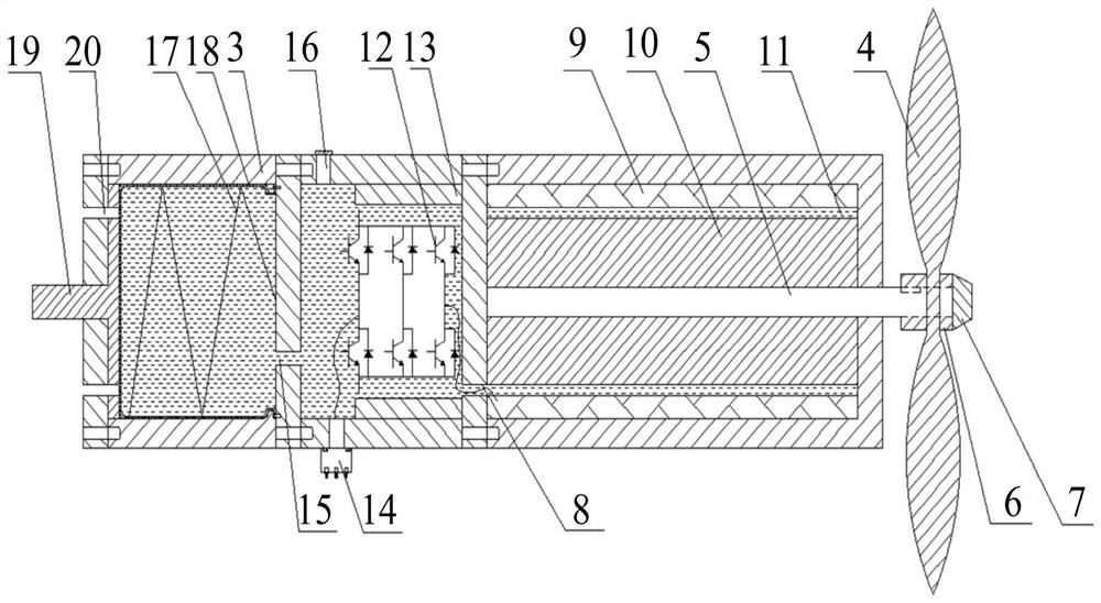
[0024] like figure 2 As shown, the present application discloses an integrated full-sea deep thruster, which includes a propeller 4 arranged outside the casing 3 and a compensation chamber, a driver chamber and a motor chamber arranged in the casing 3 and communicated in sequence. The propeller 4 of the present application is made of carbon fiber composite material through hot-press forming technology, which ensures the compactness of the structure and further reduces the overall weight. A motor is arranged in the motor cavity, and the output shaft 5 of the motor passes through the housing 3 and is connected to the propeller 4 through the lock nut 6. The diversion cap 7 is arranged outside the lock nut 6 to produce a streamlined shape and reduce resistance. A first through hole 8 is opened on the side of the motor cavity away from the prop...


PUM


Abstract

The invention discloses an integrated full-sea-depth propeller, and relates to the technical field of underwater engineering. The propeller comprises a screw propeller arranged outside a shell, a compensation cavity, a driver cavity and a motor cavity, wherein the compensation cavity, the driver cavity and the motor cavity are arranged in the shell and are sequentially connected with one another.A motor is arranged in the motor cavity, an output shaft of the motor penetrates through the shell to be connected with the screw propeller, a first through hole is formed in the side, away from the screw propeller, of the motor cavity, and the motor cavity is connected with the first side of the driver cavity through the first through hole; a driver is arranged in the driver cavity, the driver iselectrically connected with a motor outgoing line, a watertight connector is installed on the side surface of the driver cavity, and the driver is connected with external electrical equipment throughthe watertight connector; and a second through hole is formed in the second side of the driver cavity, the driver cavity is connected with the first side of the compensation cavity through the secondthrough hole, and a compensator is arranged in the compensation cavity and used for compensating external seawater pressure acting on the shell. According to the propeller, the driver and the motor are integrally designed, arrangement weight and a size can be reduced, and a fault occurrence rate is decreased.

Description

technical field [0001] The invention relates to the technical field of underwater engineering, in particular to an integrated full-sea depth thruster. Background technique [0002] When deep-sea manned submersibles (Human Occupied Vehicle, HOV) and underwater robots and other moving platforms maneuver in water, their power source is propeller. Drive the propeller to rotate, generate thrust to propel the carrier to sail. figure 1 It is a block diagram of a traditional deep-sea thruster structure, which adopts a split structure, that is, the driver and the motor are installed separately, the driver is installed in the pressure tank 1, the motor is packaged in the structural shell, and the propeller is fixed on the output shaft of the motor. The driver and the motor are connected through a watertight cable 2 to transmit electrical signals. Traditional full-sea deep thrusters have the following disadvantages: [0003] (1) The driver is installed separately in the pressure tan...

Claims


Application Information

Patent Timeline
Patent Type & Authority Applications(China)
IPC IPC(8): B63G8/08B63C11/52
CPCB63C11/52B63G8/08
Inventor 张伟李德军叶聪谢飞
Owner CHINA SHIP SCIENTIFIC RESEARCH CENTER (THE 702 INSTITUTE OF CHINA SHIPBUILDING INDUSTRY CORPORATION)
Why Eureka
Try Eureka