
Oil gas volatilization inhibition system and method with inert gas protection function

A technology for inert gas and oil and gas volatilization, which is applied in the oil and gas volatilization suppression system and the field of oil and gas volatilization suppression, which can solve problems such as uneconomical, air pollution, and unsafety, and achieve the effects of reducing direct emissions, avoiding oxygen increase, and reducing the number of openings

Pending Publication Date: 2020-10-30
眉山麦克在线设备股份有限公司
View PDF0 Cites 6 Cited by
  • Summary
  • Abstract
  • Description
  • Claims
  • Application Information

AI Technical Summary

Problems solved by technology

[0002] At present, when the vault tank is filled with oil products, the space inside the tank will decrease with the increase of oil products, and the rapid rise of pressure will cause the large breathing valve to be directly emptied. After that, the air is seriously polluted, and the oil mist formed by the discharge of high-concentration oil and gas has a huge potential safety hazard, which is easy to cause fire
When the vault tank is unloading oil products, negative pressure is formed inside the tank, and the breathing valve may move to inhale air, causing the oxygen content in the tank to exceed the standard and causing a safety hazard
At present, almost all oil vault tanks use this kind of breathing valve to balance the gas in the tank, which is uneconomical, environmentally friendly, and unsafe.

Method used


Image

  • Oil gas volatilization inhibition system and method with inert gas protection function
  • Oil gas volatilization inhibition system and method with inert gas protection function

Examples


Embodiment Construction

[0038] In order to make the purpose, technical solutions and advantages of the embodiments of the present invention clearer, the technical solutions in the embodiments of the present invention will be clearly and completely described below in conjunction with the drawings in the embodiments of the present invention. Obviously, the described embodiments It is a part of embodiments of the present invention, but not all embodiments. The components of the embodiments of the invention generally described and illustrated in the figures herein may be arranged and designed in a variety of different configurations.

[0039] Accordingly, the following detailed description of the embodiments of the invention provided in the accompanying drawings is not intended to limit the scope of the claimed invention, but merely represents selected embodiments of the invention. Based on the embodiments of the present invention, all other embodiments obtained by persons of ordinary skill in the art wi...


PUM


Abstract

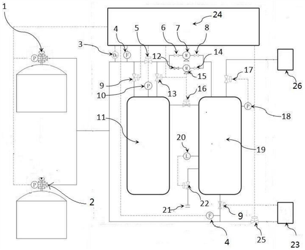
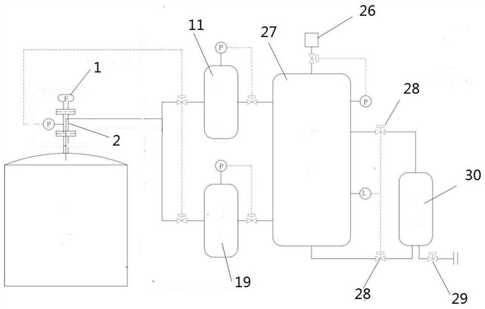
The invention belongs to the technical field of oil product storage tank safety and environmental protection, and discloses an oil gas volatilization inhibition system with an inert gas protection function. The oil gas volatilization inhibition system is applied to a storage tank for storing oil products, and comprises a buffer tank, a first gas storage tank and a first compressor, wherein the buffer tank is provided with a gas outlet and a gas inlet communicating with at least one storage tank, and the buffer tank is used for receiving redundant gas in the tank when the gas pressure in the storage tank is too high; the first gas storage tank is provided with a gas outlet and a gas inlet communicating with the gas outlet of the buffer tank, and the first gas storage tank is used for discharging gas in the first gas storage tank into the storage tank through the gas outlet of the first gas storage tank when the gas pressure in the storage tank is too low. The invention further disclosesan oil gas volatilization inhibition method with the inert gas protection function. According to the oil gas volatilization inhibition system and method with the inert gas protection function, when the pressure of the tank top is unbalanced, original oil gas in the tank can be used for rapid supplementing and adjusting, so that the balance is achieved again, the breathing action of a breathing valve can be prevented, the purposes of energy conservation and emission reduction are achieved, and inert protection can be carried out on the storage tank.

Description

technical field [0001] The invention belongs to the technical field of safety and environmental protection of oil storage tanks, and in particular relates to an oil and gas volatilization suppression system with an inert gas protection function and an oil and gas volatilization suppression method with an inert gas protection function. Background technique [0002] At present, when the vault tank is filled with oil products, the space inside the tank will decrease with the increase of oil products, and the rapid rise of pressure will cause the large breathing valve to be directly emptied. Afterwards, the air is seriously polluted, and the oil mist formed by the discharge of high-concentration oil and gas has a huge safety hazard, which is easy to cause a fire. When the vault tank is unloading oil products, negative pressure is formed inside the tank, and the breathing valve may operate to inhale air, causing the oxygen content in the tank to exceed the standard and causing a ...

Claims


Application Information

Patent Timeline
IPC IPC(8): B65D90/32B65D90/44B65D90/30
CPCB65D90/32B65D90/44B65D90/30
Inventor 郭继红李军豆建笃张艺山
Owner 眉山麦克在线设备股份有限公司
Learn More