
Material conveying system capable of automatically overturning circulating trolley

A conveying system and self-turning technology, applied in conveyors, mechanical conveyors, transportation and packaging, etc., can solve the problem of waste of travel space, and achieve the effect of convenient construction, saving construction cost and compact structure

Pending Publication Date: 2020-10-30
HUNAN UNIV OF TECH
View PDF0 Cites 0 Cited by
  • Summary
  • Abstract
  • Description
  • Claims
  • Application Information

AI Technical Summary

Problems solved by technology

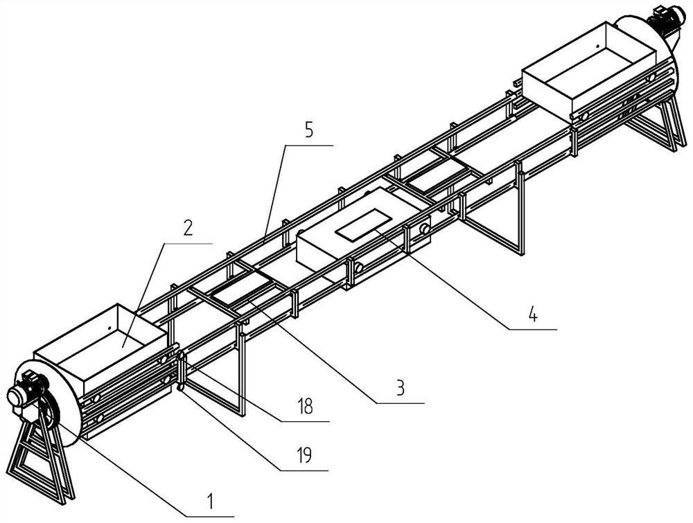
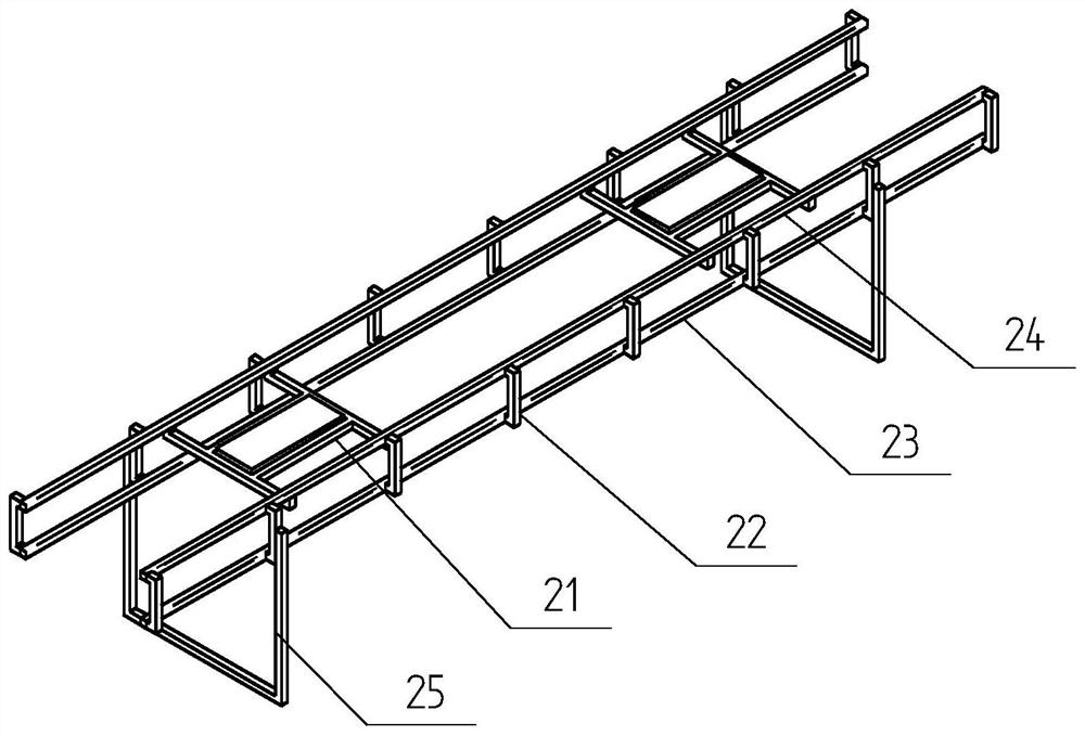
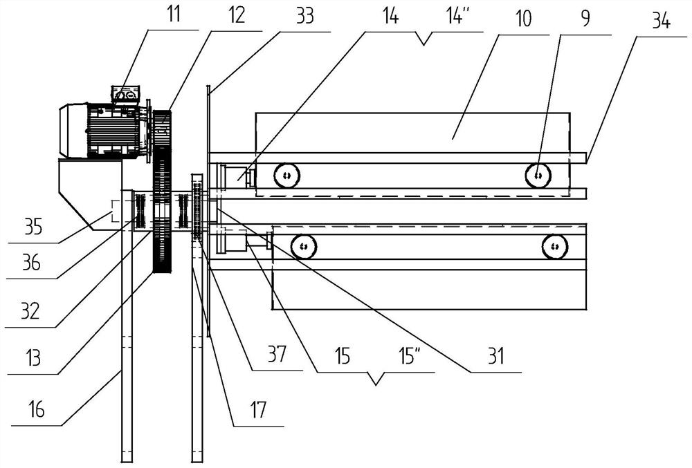
[0006] For this reason, the present invention proposes a material conveying system of a self-turning cycle trolley, and achieves the following beneficial aspects: 1. The use of a linear motor drive eliminates the disadvantages of wear, failure, and noise caused by mechanical transmission; 2. Magnetic power materials The trolley, walking guide and drive rail modules all adopt modular design, and the quantity can be increased or decreased according to actual needs to achieve the purpose of adjusting the transport volume and adjusting the conveying distance; 3. The automatic flip design solves the waste of travel space in the reciprocating process of traditional material transport vehicles problems, and make full use of the driving force of the linear motor, which can meet the requirements of larger line ramps and smaller line curve radius

Method used


Image

  • Material conveying system capable of automatically overturning circulating trolley
  • Material conveying system capable of automatically overturning circulating trolley
  • Material conveying system capable of automatically overturning circulating trolley

Examples


Embodiment 12

[0057] Example 1.2, as in Image 6 As shown, a material conveying system with a self-turning cycle trolley is different from Example 1.1 in that the conveying track (6) includes several sets of walking guides and drive rail modules (5), and a magnetic power material trolley (2) is added at the same time. The number of modules is applicable to the working conditions with large transportation volume and long distance.

[0058] In the above-mentioned embodiment, the working process of a material conveying system of a self-turning cycle trolley provided by the present invention is as follows: Figure 7 , 8 , 9, the specific description is as follows:

[0059] a) When the empty magnetic power material trolley (2) arrives at the material receiving end along the down track, the entry detection sensor J1 (19) detects a signal, the buffer stroke cylinder solenoid valve A2 (15') is energized, and the buffer stroke cylinder (15') ) is slowly retracted under the impact of the magnetic ...


PUM


Abstract

The invention provides a material conveying system capable of automatically overturning a circulating trolley. The material conveying system mainly comprises two automatic turnover mechanisms, a conveying track, a magnetomotive material trolley, bidirectional linear motors and an induction plate. The two automatic turnover mechanisms are arranged at two ends of the conveying track respectively; the conveying track is composed of a plurality of sets of traveling guide and driving track modules; the induction plate is installed at the bottom of a magnetomotive material trolley; and the bidirectional linear motors are installed on the traveling guide and driving track modules and are used for driving the magnetomotive material trolley to run in two directions along an upper traveling rail anda lower traveling rail. According to the material conveying system, the traveling guide and driving track modules and the magnetomotive material trolley are designed in a modularization mode, and thequantity of the traveling guide and driving track modules and the magnetomotive material trolley can be increased and decreased according to actual working condition requirements, so that the purposes of adjusting the length and the transportation quantity of a transmission line are achieved, the material conveying system is applicable to various working conditions and situations, and the transportation and transmission process is efficient and reliable.

Description

technical field [0001] The invention relates to the technical field of magnetic power material conveying, in particular to a material conveying system of a self-turning cycle trolley. . Background technique [0002] At present, belt conveyors are generally used as the main equipment for bulk material transportation in projects such as open-pit mines, thermal power plants, and docks. With the improvement of production capacity, the demand for long-distance and large-volume material transportation is increasing. Long-distance transportation will inevitably have the problem of complex and changeable line conditions, so higher requirements are also put forward for transportation. [0003] The existing belt conveyors have the following deficiencies in long-distance transportation: belts and rollers are prone to wear and tear, the length of the belt cannot be adjusted according to different placement positions of materials, the conveying angle is small, and the radius of the cur...

Claims


Application Information

Patent Timeline
Patent Type & Authority Applications(China)
IPC IPC(8): B65G35/00
CPCB65G35/00
Inventor 张灵邱显焱卜旦霞
Owner HUNAN UNIV OF TECH
Learn More