Cabinet equipment installation lifter

A technology for equipment installation and lifts, which is applied in the field of lifts, can solve problems such as maintenance troubles, accidents, and high costs, and achieve the effects of convenient installation and maintenance, increased load capacity, and improved stability

Inactive Publication Date: 2020-10-30
NANYANG POWER SUPPLY COMPANY OF STATE GRID HENAN ELECTRIC POWER
View PDF6 Cites 0 Cited by
  • Summary
  • Abstract
  • Description
  • Claims
  • Application Information

AI Technical Summary

Problems solved by technology

[0002] The installation of traditional cabinet equipment often requires the staff to carry the cabinet equipment to a high place by lifting the shoulders. The workflow is cumbersome and inefficient, and the weight of the cabinet equipment is relatively large. It is easy to cause accidents when moving upwards by manpower, so a lift is needed. Installation of auxiliary cabinet equipment
[0003] The Chinese invention patent with the notification number CN100515917 discloses a scissor lift, which includes a platform, a chassis, a scissor arm, an oil cylinder, upper and lower cross braces, a connecting rod, and a hydraulic system; the two scissor arms are rotated in the center to form a scissor; The upper and lower ends of the two scissor arms of the scissors are connected with the platform and the chassis respectively in rotation and sliding; the upper and lower cross braces are respectively connected with the corresponding scissor arms of the front and rear scissors; the cylinder body of the oil cylinder is rotationally connected with the lower cross brace; One end is rotationally connected with the piston rod of the oil cylinder, and the other end is connected with the upper cross brace; the other end of the connecting rod connected with the upper cross brace is farther away from the center of the scissor arm than the end connected with the piston rod. This invention only needs a lower pressure Hydraulic oil can lift heavy objects with a small thrust, but the structure is complex and the cost is high. The device involved in this invention requires precise hydraulic transmission, which is costly, troublesome to install and maintain, and cannot be used in places with large temperature differences. local use
[0004] The Chinese utility model patent with the notification number CN 208964473 U discloses a lift, including: a main frame, a sliding frame, a bracket and a movable and fixed pulley block mechanism; the bracket is arranged on the sliding frame; the sliding frame is clamped in the main frame; The movable and fixed pulley block mechanism includes: a movable pulley, a first fixed pulley, a second fixed pulley, a first steel wire rope and a second steel wire rope; the movable pulley is fixed on the bottom of the sliding frame; the first fixed pulley is fixed on the top of the main frame; The first fixed pulley and the movable pulley are fixed on the main frame; the second fixed pulley is fixed on the top of the sliding frame and connected in series with the second steel wire rope; the two ends of the second steel wire rope are connected with the bracket and the bottom of the main frame connection, the elevator has high construction efficiency and low cost, but the load-bearing surface is perpendicular to the main frame, the load-bearing capacity is small, and the number of pulleys used is large, which is easy to wear during use and troublesome to maintain

Method used


Image

  • Cabinet equipment installation lifter
  • Cabinet equipment installation lifter
  • Cabinet equipment installation lifter

Examples


Embodiment 1

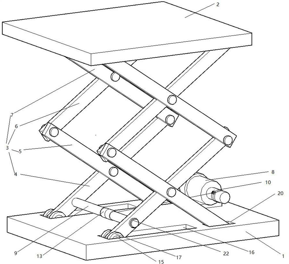
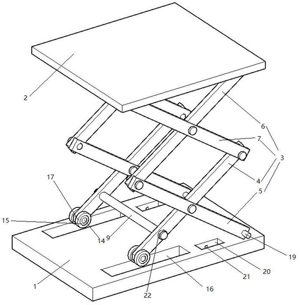
[0031] Such as figure 1 with figure 2 Shown as the first embodiment of the present invention, a cabinet equipment installation elevator includes a base 1, a carrying platform 2, and two sets of scissor-like support arms 3 between the base and the carrying platform. The first connecting rod 4, the second connecting rod 5, the third connecting rod 6 and the fourth connecting rod 7 are hinged to each other in a scissor type. The bottom ends of the first connecting rod 4 are welded with steel connecting shaft 14 respectively. The connecting shaft 14 is provided with a roller 15 outside. The roller 15 is a roller bearing. The inner peripheral surface of the roller 15 is fixed on the connecting shaft 14 by glue or welding. The base 1 is machined by a lathe to match the two rollers 15 Slide groove 16, the outer peripheral surface of the roller 15 is in contact with the bottom surface of the slide groove 16, in order to increase the friction between the roller 15 and the slide groove 1...

Embodiment 3

[0036] Such as Figure 4 Shown is the third embodiment of the present invention. The difference between this embodiment and the first embodiment is that the ends of the two connecting shafts 14 are respectively fixed by bolts to the universal ball 18, the universal ball 18 and the sliding groove 16 The two side walls are in contact.

Embodiment 4

[0038] Such as Figure 5 Shown is the fourth embodiment of the present invention. The difference between this embodiment and the first embodiment is that a bearing 23 is provided on the connecting shaft 19, the bearing 23 is a roller bearing, and the inner circumferential surface of the bearing 23 is fixed by glue On the outer peripheral surface of the connecting shaft two 14, the part above the insertion hole 21 is then cut off by a cutting machine, the outer circumferential surface of the bearing 23 is fixed to the inner peripheral surface of the insertion hole 21 with glue, and then the cut part is glued with glue Back.


PUM


Abstract

The invention discloses a cabinet equipment installation lifter. The cabinet equipment installation lifter comprises a base, a bearing platform, two scissor-type supporting arms located between the base and the bearing platform, and a driving mechanism for driving the supporting arms to be unfolded or folded relatively; each supporting arm is composed of a first connecting rod, a second connectingrod, a third connecting rod and a fourth connecting rod; the driving mechanism comprises a motor, a transverse rod and a connecting rope arranged between the motor and the transverse rod; and the transverse rod is arranged between the lower parts of the two first connecting rods, the bottom ends of the first connecting rods are in sliding connection with the base, and the bottom ends of the second connecting rods are in rotating connection with the base. The cabinet equipment installation lifter is is convenient to install and maintain, and low in cost.

Description

Technical field [0001] The invention relates to the field of elevators, in particular to a cabinet equipment installation elevator. Background technique [0002] The installation of traditional cabinet equipment often requires workers to carry the cabinet equipment to a high place by lifting their shoulders. The work flow is cumbersome, the efficiency is low, and the weight of the cabinet equipment is relatively large. It is prone to accidents when moving upwards by manpower. Therefore, a lift is required. Installation of auxiliary cabinet equipment. [0003] The Chinese invention patent with the announcement number CN100515917 announced a scissor lift, which includes a platform, a chassis, a scissor arm, an oil cylinder, upper and lower cross braces, a connecting rod, and a hydraulic system; the two scissor arms rotate in the center to form a scissor; The upper and lower ends of the two scissor arms of the scissor fork are rotated and slidably connected with the platform and the ...

Claims


Application Information

Patent Timeline
Patent Type & Authority Applications(China)
IPC IPC(8): B66F7/06B66F7/08B66F7/28
CPCB66F7/0666B66F7/085B66F7/28
Inventor 白献甫白献春
Owner NANYANG POWER SUPPLY COMPANY OF STATE GRID HENAN ELECTRIC POWER
Why Eureka
Try Eureka