Fluidized bed gasification furnace deslagging method and device

A fluidized bed gasifier and gasifier technology, which are applied in the field of coal gasification, can solve the problem that the bed height of the gasifier cannot be maintained constant, the slag bucket is overheated, and the safety and stability of the pressurized fluidized bed gasifier cannot be realized. Slag discharge and other issues

Pending Publication Date: 2020-10-30
INST OF ENGINEERING THERMOPHYSICS - CHINESE ACAD OF SCI
View PDF0 Cites 2 Cited by
  • Summary
  • Abstract
  • Description
  • Claims
  • Application Information

AI Technical Summary

Problems solved by technology

This slag discharge method controls the flow rate of the cooling gas in the slag discharge pipe to control the slag discharge amount. The flow rate increases and the slag discharge amount decreases, and the flow rate decreases. Fluctuations in the amount of gasification make it impossible to maintain a constant bed height of the gasifier, and fluctuations in the operating conditions of the gasifier affect the gasification index
In addition, increasing the amount of slag discharge also has the risk

Method used


Image

  • Fluidized bed gasification furnace deslagging method and device
  • Fluidized bed gasification furnace deslagging method and device
  • Fluidized bed gasification furnace deslagging method and device

Examples


Embodiment 1

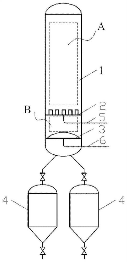
[0061] In Embodiment 1 of the present invention, a fluidized bed gasifier slagging device is provided, such as figure 1 As shown, the device used includes a gasifier 1, a slag hopper 4 and a gasification agent air distribution device 2 located at the lower part of the gasifier 1. The gasifier 1 and the slag hopper 4 are connected through a slag discharge pipe, and also include : the ash and slag cooling zone B arranged at the lower part of the air distribution device 2, the slag discharging machine 3 arranged in the ash and slag cooling zone B, the slag discharging machine 3 is provided with an air distribution pan 10 for feeding cooling gas. The gasification agent required for the gasification reaction is introduced into the air distribution device 2 through the main air pipe 5 and then passed into the gasification furnace 1 . The cooling gas passes into the slag discharger 3 through the cooling air pipe 6, and enters the ash cooling zone B from the air distribution pan 10 of...

Embodiment 2

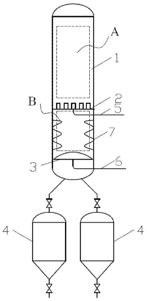
[0065] Such as figure 2 As shown, the fluidized bed gasifier slagging device provided by Example 2 of the present invention has the same structure as that of Example 1, the difference is that in order to better realize ash cooling, heat exchange is arranged in the ash cooling zone B The tubes 7 and the heat exchange tubes 7 can be arranged tubes or serpentine tubes. From the perspective of facilitating material drop and wear resistance, serpentine heat exchange tubes with fins are preferred. The heat exchange tubes 7 are arranged in multiple groups along the circumferential direction. In order to prevent slag from bridging on the heat exchange tubes 7, the distance between two adjacent groups of heat exchange tubes 7 is 80mm-150mm. In order to prevent steam from condensing on the wall of the heat exchange tube 7, the cooling gas in the heat exchange tube 7 is preferably synthesis gas. From the perspective of reducing the wear of the heat exchange tube 7, the superficial veloc...

Embodiment 3

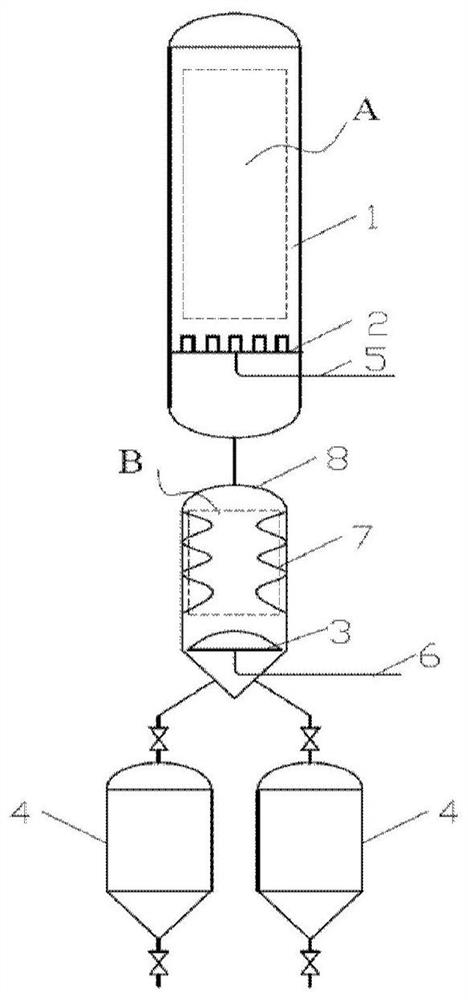
[0067] Such as image 3 As shown, the fluidized bed gasifier slagging device provided in Example 3 of the present invention has the same structure as that of Example 1, the difference is that the ash is cooled by the slag cooler 8, and snakes are arranged inside the slag cooler 8. A slag discharger 3 is installed at the bottom, and the slag cooler 8 is connected to the gasifier 1 through the slag discharge pipe. The hot ash generated by gasification enters the slag cooler 8 through the slag discharge pipe, The cooling gas is in countercurrent contact, and under the disturbance of the cooling gas, it rapidly exchanges heat with the heat exchange tube to obtain cooling (the process flow is the same as that of Example 2).


PUM


Abstract

The invention discloses a fluidized bed gasification furnace deslagging method and a device, and the fluidized bed gasification furnace deslagging device comprises a gasification furnace, wherein oneregion in the gasification furnace is defined as a gasification reaction region and is used for carrying out a gasification reaction; an ash cooling area which is communicated with the gasification reaction region, wherein cooling gas is introduced into the ash cooling area; and a slag discharging machine which is arranged in the ash cooling area and is used for quantitatively discharging ash slaggenerated by the gasification reaction. By arranging the ash cooling area communicated with the gasification reaction region and arranging the slag discharging machine in the ash cooling area, the problems of sealing leakage and operation faults of the slag discharging machine at high temperature are effectively solved, and high-temperature ash generated by the pressurized fluidized bed gasification furnace is cooled, quantified and stably discharged.

Description

technical field [0001] The invention relates to the technical field of coal gasification, in particular to a method and device for removing slag from a fluidized bed gasification furnace. Background technique [0002] Fluidized bed gasification technology, as a clean coal conversion technology, is gradually developing towards high pressure and large-scale. The increase in operating pressure has brought about the technical problem of high-temperature ash and slag removal. At present, there are two main methods of slag removal in fluidized bed gasification technology: [0003] One is to use mechanical cooling, generally using a drum cooling slag machine. The hot ash and circulating cooling water complete the heat exchange in the form of indirect heat exchange in the slag cooling machine to realize the cooling of the hot ash. Machine rotation speed control. When this method is operated under high temperature and high pressure, the sealing part of the connection parts of each ...

Claims


Application Information

Patent Timeline
IPC IPC(8): C10J3/56C10J3/72
CPCC10J3/56C10J3/72
Inventor 湛月平董鹏飞王东宇朱治平
Owner INST OF ENGINEERING THERMOPHYSICS - CHINESE ACAD OF SCI
Why Eureka
Try Eureka