
Blast furnace iron runner erosion detection system and method

A detection method and detection system technology, applied in the direction of inspection devices, discharge devices, etc., can solve the problems of easy damage of temperature sensors, low accuracy of appearance monitoring, and susceptibility to interference

Pending Publication Date: 2020-10-30
ZHENGZHOU SAIWO TECH CO LTD
View PDF1 Cites 1 Cited by
  • Summary
  • Abstract
  • Description
  • Claims
  • Application Information

AI Technical Summary

Problems solved by technology

[0003] Due to the high temperature of the iron trench, the temperature sensor is easily damaged and easily disturbed, the appearance monitoring accuracy is low, and the labor intensity is high

Method used


Image

  • Blast furnace iron runner erosion detection system and method
  • Blast furnace iron runner erosion detection system and method
  • Blast furnace iron runner erosion detection system and method

Examples


Embodiment 1

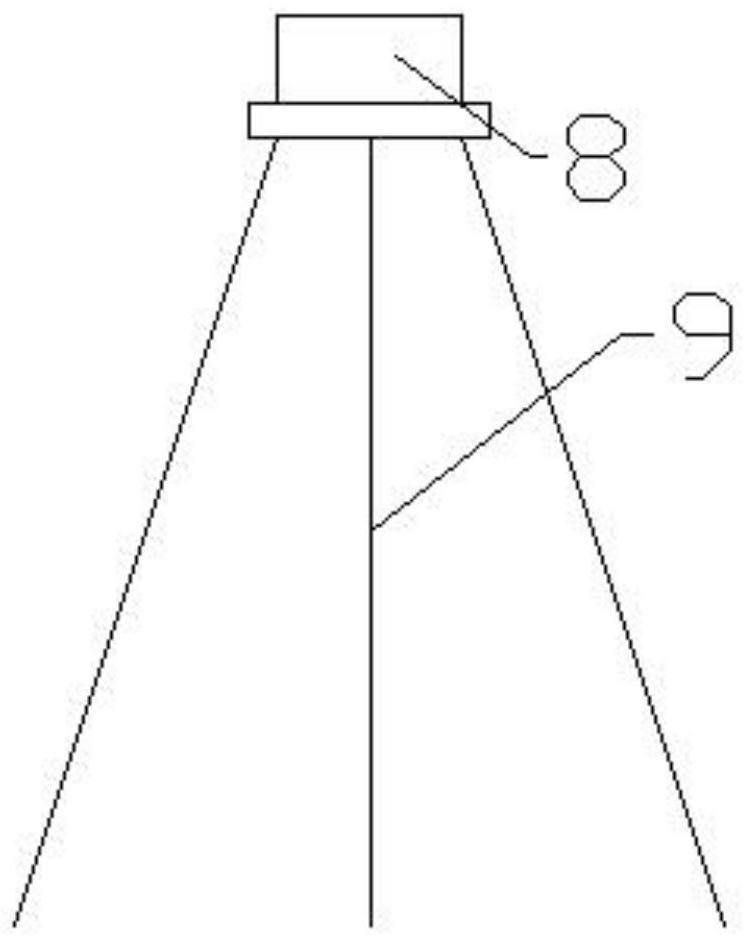
[0028] Such as Figure 1-8 As shown, a blast furnace iron trench erosion detection system includes an image acquisition device and a server. The image acquisition device includes a bracket 9, and a 3D scanner 8 is installed on the upper end of the bracket. The 3D scanner is connected to the server signal, and the image acquisition device can be used from multiple Image acquisition is performed on the iron trench from different angles, and the server is a PC. Specifically, the 3D scanner has at least 6 scanning points. Overlay 3D scanning to get a complete 3D model.

[0029] After the production of the new iron trench is completed, and after each tapping is completed and the residual iron is placed, 3D scanning is carried out, and the 3D model of the working face of the iron trench is converted from the image obtained through the 3D scanning. By comparing the 3D models in each The coordinate change value of the point is obtained to obtain the erosion value of the iron trench. ...


PUM


Abstract

The invention relates to a blast furnace iron runner, in particular to a blast furnace iron runner erosion detection system and method. The blast furnace iron runner erosion detection system comprisesan image collecting device and a server. The image collecting device comprises a support, a 3D scanner is arranged at the upper end of the support and is in signal connection with the server, and theimage collecting device can conduct image collecting on the iron runner from multiple angles. The server is a PC, non-contact image information collection is conducted through a camera, then the erosion state of the iron runner is obtained through picture comparison analysis, convenience and practicability are achieved, the detection precision is high, the labor intensity is low, scanning is conducted from multiple angles, the iron runner can be completely covered, and the detection precision is improved.

Description

technical field [0001] The invention relates to a blast furnace iron trench, in particular to a blast furnace iron trench erosion detection system and method. Background technique [0002] The blast furnace iron trough is the main equipment for blast furnace work. The molten iron of the blast furnace flows out through the iron trough, which severely corrodes the iron trough, especially the main trough, where the flow of molten iron is large. Different corrosion resistance brings troubles to the erosion monitoring of blast furnace iron trough. The existing monitoring method is to monitor the temperature monitoring and appearance monitoring. The temperature monitoring is to install a temperature sensor on the side wall of the iron trough to monitor the temperature in real time. , when the detected temperature exceeds the preset value, an alarm is issued; the appearance monitoring is to observe the state of the inner wall of the iron ditch when the furnace is shut down, and the...

Claims


Application Information

Patent Timeline
IPC IPC(8): C21B7/24C21B7/14
CPCC21B7/14C21B7/24
Inventor 李星燃熊小勇
Owner ZHENGZHOU SAIWO TECH CO LTD
Learn More