
Self-cleaning pressure resistance sliding door device for coal transfer station

A transfer station and self-cleaning technology, applied in the cleaning method using tools, the suspension device of the wing leaf, the arrangement of the leaf leaf, etc., can solve the problems of sliding track wear, sliding obstruction, and easy deformation of sliding doors, etc., to reduce Frictional resistance, the effect of avoiding deformation

Inactive Publication Date: 2020-10-30
李洪伟
View PDF1 Cites 0 Cited by
  • Summary
  • Abstract
  • Description
  • Claims
  • Application Information

AI Technical Summary

Problems solved by technology

[0007] In order to solve the above technical problems, the present invention provides a self-cleaning pressure-resistant sliding door device for coal transfer stations to solve the existing problem that the sliding frame of the sliding door in the existing device has weak compressive resistance, especially for transfer The sliding door used in the station is prone to deformation after being repeatedly rolled by the vehicle, which leads to the phenomenon of sliding obstruction; moreover, when the rollers of the existing sliding door are severely worn, the roller support seat is easy to contact with the bottom end surface of the sliding track, resulting in sliding. The bottom surface of the track is severely worn, and the new rollers are likely to wear out quickly after the replacement of new rollers; finally, the sliding track of the existing device is prone to accumulation of residues, and it cannot be automatically cleaned during the sliding process of the door panel

Method used


Image

  • Self-cleaning pressure resistance sliding door device for coal transfer station
  • Self-cleaning pressure resistance sliding door device for coal transfer station
  • Self-cleaning pressure resistance sliding door device for coal transfer station

Examples


Embodiment

[0037] as attached figure 1 to attach Figure 9 Shown:

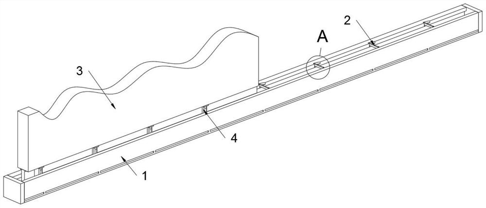
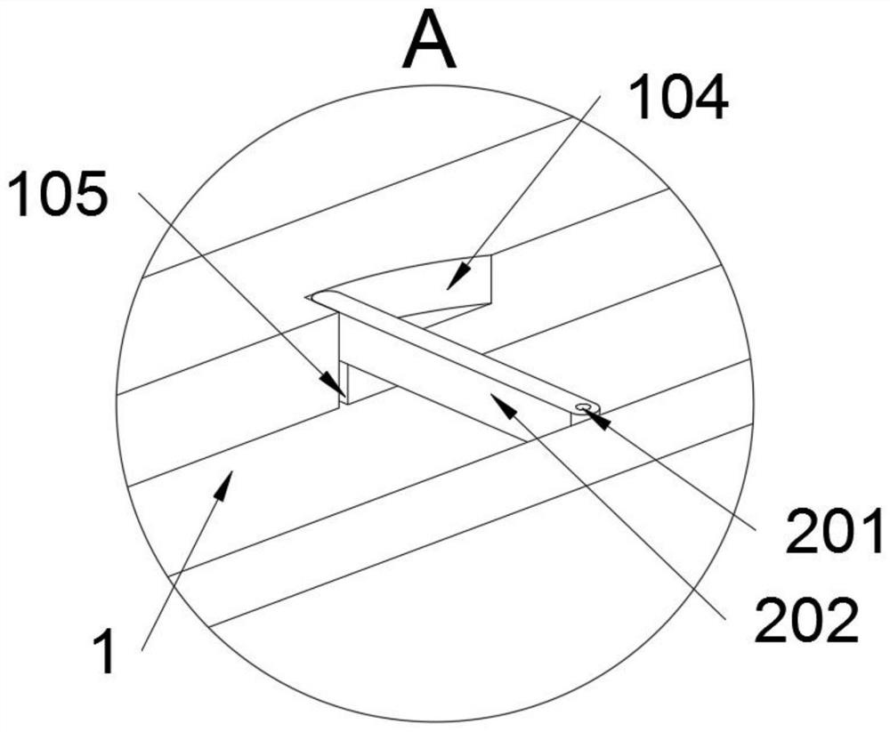
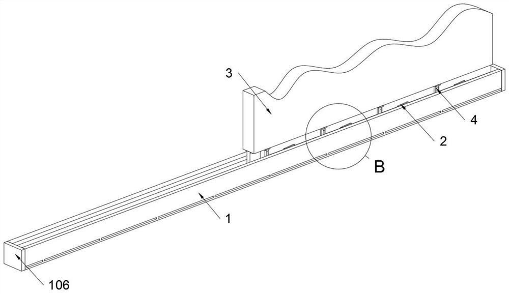
[0038] The present invention provides a self-cleaning pressure-resistant sliding door device for a coal transfer station, including a sliding track 1, a door panel 3 and a roller seat 401; the bottom surface of the door panel 3 is fixedly connected with a roller structure 4 in a rectangular array, and the door panel 3 passes The roller structure 4 is slidingly connected in the sliding track 1, and the bottom surface of the door panel 3 is symmetrically fixed with two cleaning structures 5 through bolts; the sliding track 1 is fixed on the ground, and the sliding track 1 is equipped with an elastic support structure 2; refer to for example figure 1 with figure 2 , the elastic support structure 2 includes a rotating shaft 201 and a support arm 202. There are four rotating shafts 201 in total, and the four rotating shafts 201 are all rotatably connected to the sliding track 1, and the tail ends of the four rotating shaft...


PUM


Abstract

The invention provides a self-cleaning pressure resistance sliding door device for a coal transfer station, and relates to the technical field of industrial doors. The problems that a sliding door islikely to be deformed after being repeatedly rolled by vehicles, then the sliding blocking phenomenon is caused, after rolling wheels are severely worn, rolling wheel supporting seats are likely to make contact with the bottom end face of a sliding track to severely wear the bottom end face of the siding track, therefore, new rolling wheels are rapidly worn after replacing the worn rolling wheels,and automatic cleaning cannot be achieved in a door plate sliding process are solved. The self-cleaning pressure resistance sliding door device for the coal transfer station comprises a sliding trackand rolling wheel seats, and the bottom end face of a door plate is fixedly connected with a rolling wheel structure in a rectangular array shape. Since supporting arms are installed on rotating shafts, the tail ends of the rotating shafts are provided with coil springs, under the pull, the supporting arms and clamping grooves are in a clamped state, at the moment, the sliding track is in a supporting state, and therefore the sliding track can be effectively prevented from being deformed when rolled by vehicles.

Description

technical field [0001] The invention belongs to the technical field of industrial gates, and more specifically relates to a self-cleaning anti-pressure sliding door device for a coal transfer station. Background technique [0002] Industrial sliding doors are small and medium-sized sliding doors mainly suitable for factories, warehouses and other places. Since sliding doors do not occupy the interior space of factories, they have the advantages of simple structure and stable operation. They are currently one of the most widely used industrial doors. [0003] For example, the application number: CN201621417180.4, this utility model discloses an industrial sliding door, including a door leaf, an upper guide system, a lower load-bearing system and a sealing system. The upper end of the door leaf is provided with a number of door frames connected to each other by bolts, and the bottom of the door leaf There are inspection doors and pass-through doors. The upper guide system incl...

Claims


Application Information

Patent Timeline
IPC IPC(8): E06B3/46E06B7/28E05D13/00B08B1/00
CPCE06B3/4636E06B7/28E05D13/00B08B1/30
Inventor 李洪伟
Owner 李洪伟
Learn More