Speed reducer, driving device and rotary drilling rig

A technology for a rotary drilling rig and a driving device, which is applied in the field of driving devices, rotary drilling rigs and reducers, can solve the problems of small expansion space of hydraulic oil, affecting the sealing performance of sealing rings, and small size of hydraulic motor, so as to improve construction efficiency, The effect of increasing service life and reducing maintenance costs

Pending Publication Date: 2020-10-30
BEIJING SANY INTELLIGENT MFG TECH CO LTD
View PDF0 Cites 0 Cited by
  • Summary
  • Abstract
  • Description
  • Claims
  • Application Information

AI Technical Summary

Problems solved by technology

Instantaneous and continuous high speed will increase the temperature of the hydraulic oil in the hydraulic motor. Due to the small size of the hydraulic motor and the small expansion space of the hydraulic oil, the high temperature and high pressure hydraulic oil will cause the deformation of the sensor and affect the sealing of the sealing ring, which will cause the motor to Oil drainage failures increase maintenance costs and seriously affect customer construction efficiency

Method used


Image

  • Speed reducer, driving device and rotary drilling rig
  • Speed reducer, driving device and rotary drilling rig
  • Speed reducer, driving device and rotary drilling rig

Examples


Embodiment 1

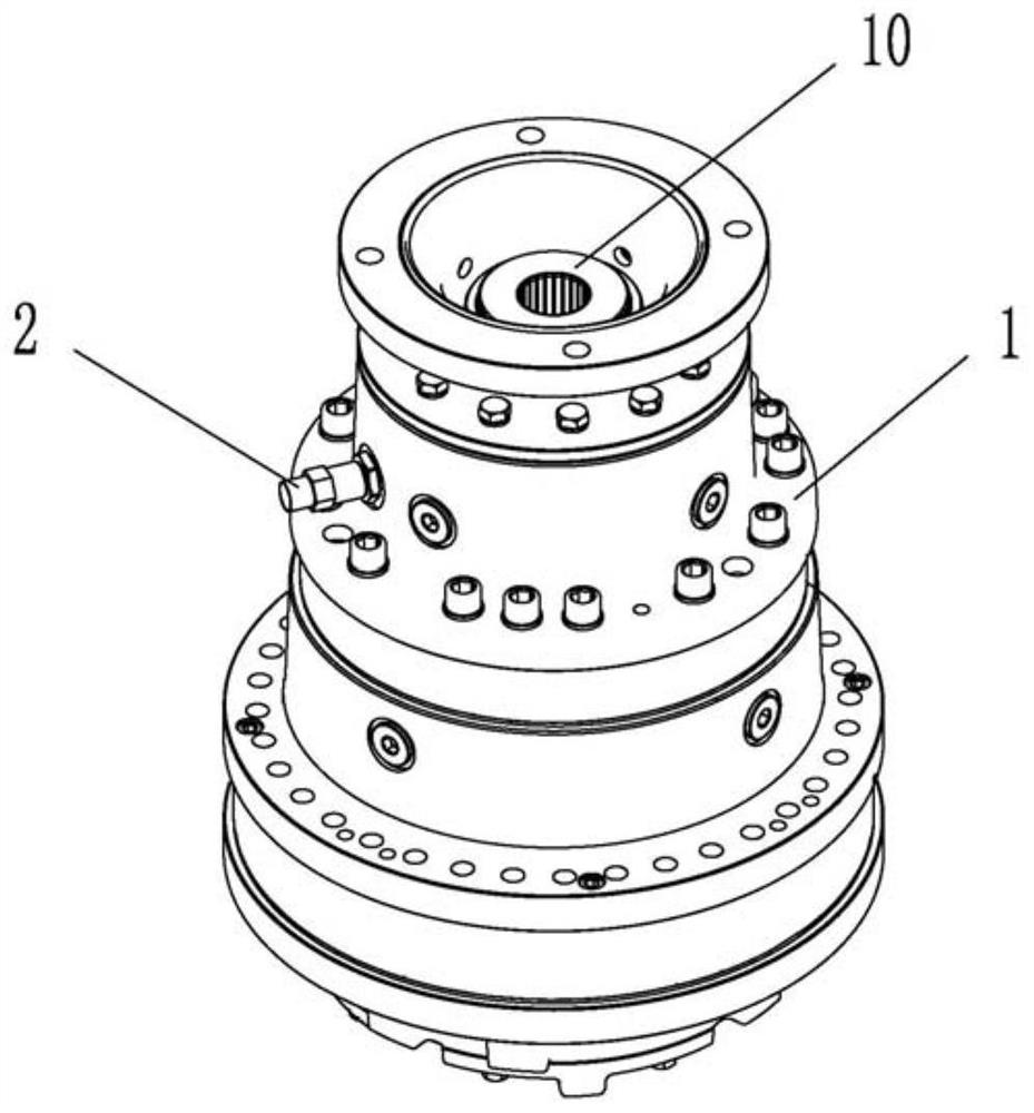
[0035] see figure 1 , The speed reducer provided in this embodiment can be applied to a rotary drilling rig, and of course it can also be used in other construction machinery. This embodiment will take a rotary drilling rig as an example to describe in detail.

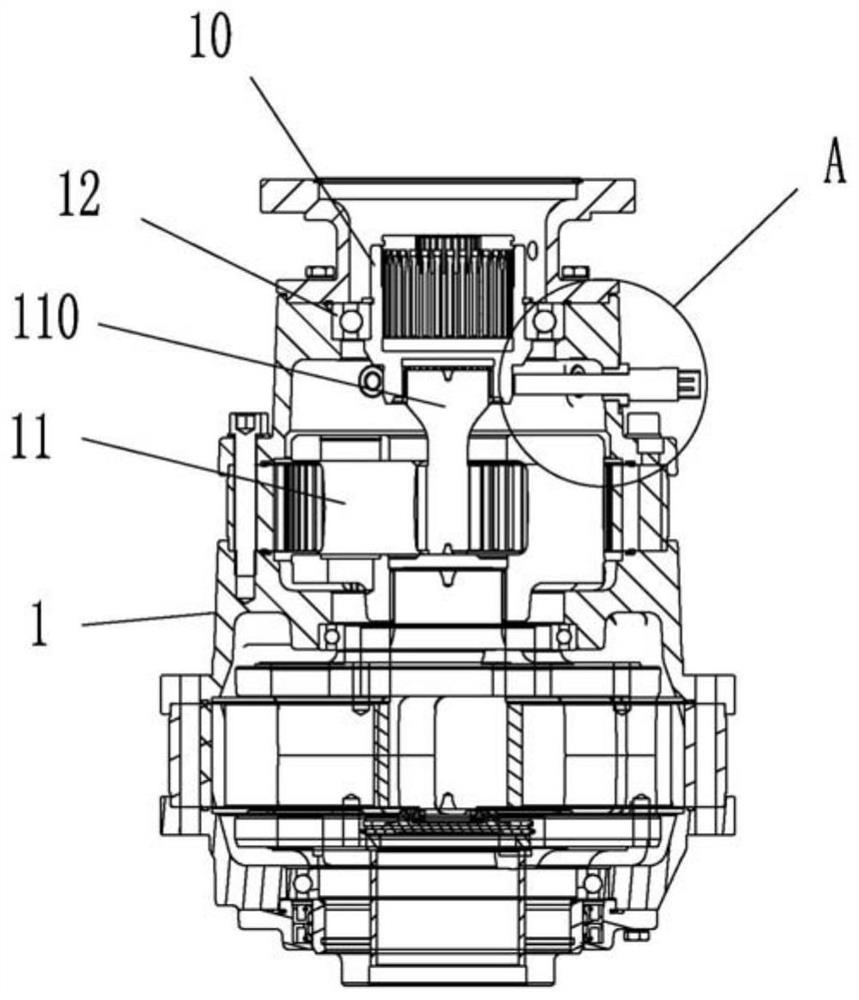
[0036] see again figure 2 The reducer provided in this embodiment includes a housing 1 and a transmission assembly 11, the transmission assembly 11 is disposed in the housing 1, and the transmission assembly 11 includes an input shaft 110 and an opposite output shaft (not shown). The input end of the input shaft 110 is used for power input, and the input power enters the transmission assembly 11 through the input shaft 110, and then is output by the output shaft of the transmission assembly 11, wherein the output power is the power for decelerating and increasing torque.

[0037] see again Figure 4 , further, the input shaft 110 is arranged in the casing 1, the input end of the input shaft 110 is provided with a co...

Embodiment 2

[0051] see Figure 1-Figure 4 , this embodiment provides a reducer, which can be applied to rotary drilling rigs, and is an improvement on the basis of Embodiment 1. Compared with Embodiment 1, the main difference is:

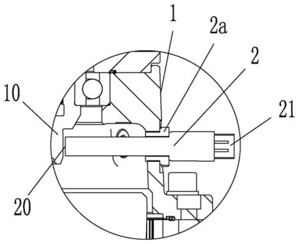
[0052] In this embodiment, protrusions (not shown) are uniformly provided on the circumference of the connecting sleeve 10 , and it can be understood that the height of the protrusions on the connecting sleeve 10 varies.

[0053] Wherein, the sensing end 20 of the sensor 2 faces the position where the connection sleeve 10 is provided with a protrusion, and is used for sensing the height change of the position where the connection sleeve 10 is provided with the protrusion.

[0054] This embodiment is an improvement on the basis of Embodiment 1, so this embodiment also has the following advantages: By setting the sensor 2 on the housing 1 of the reducer to measure the speed of the input shaft 110 of the reducer, power can be obtained indirectly Speed ​​of entry ...

Embodiment 3

[0056] see Figure 1-Figure 4 , this embodiment provides a reducer, which can be applied to rotary drilling rigs. It is an improvement made on the basis of Embodiment 1 or Embodiment 2. Compared with Embodiment 1 or Embodiment 2, the main difference is:

[0057] In this embodiment, the connection sleeve 10 and the input shaft 110 cooperate with each other through flat keys, wherein the connection sleeve 10 is provided with a first key groove, and the input shaft 110 is provided with a second key groove. During installation, the flat key is installed in the second keyway, and then the connecting sleeve 10 is installed so that the first keyway on the connecting sleeve 10 is aligned with the flat key.

[0058] This embodiment is an improvement on the basis of Embodiment 1 or Embodiment 2, so this embodiment also has the following advantages: by setting the sensor 2 on the housing 1 of the reducer to measure the speed of the input shaft 110 of the reducer, The speed of the power ...


PUM


Abstract

The invention provides a speed reducer, a driving device and a rotary drilling rig, and relates to the technical field of rotary drilling rigs. The speed reducer comprises a shell and an input shaft,wherein the input shaft is arranged in the shell, the input end of the input shaft is provided with a connecting sleeve, the circumferential direction of the connecting sleeve is uniformly provided with protrusions or grooves, the position, corresponding to the connecting sleeve, of the shell is provided with a sensor, the sensing end of the sensor extends into the shell, and the sensing end senses the height difference change of the protrusions or the grooves to obtain the rotation speed of the input end. The driving device uses the speed reducer, and the rotary drilling rig uses the drivingdevice. According to the speed reducer, the driving device and the rotary drilling rig, the sensor is arranged on the shell of the speed reducer to measure the speed of the input shaft of the speed reducer, the sensor is no longer affected by temperature, and the problem of hydraulic oil leakage is avoided. In addition, the sensor is no longer affected by the temperature, the service life is prolonged, meanwhile, the maintenance cost is reduced, and then the construction efficiency is improved.

Description

technical field [0001] The invention relates to the technical field of rotary drilling rigs, in particular to a speed reducer, a driving device and a rotary drilling rig. Background technique [0002] Rotary drilling rig is a large-caliber and high-efficiency hole-forming equipment used in foundation construction. It uses vertically arranged drill pipes to directly rotate and excavate the ground, thereby quickly forming pile holes of required diameter and depth on the ground. [0003] At present, the solutions for measuring the speed of the power head of the rotary drilling rig are all on the hydraulic motor, and the sensor is installed on the motor housing corresponding to the output shaft of the hydraulic motor. The main engine provides high-pressure hydraulic oil to the hydraulic motor, and the motor converts hydraulic energy into mechanical energy, and provides power to the power head through the reducer. [0004] However, the rotational speed of the output shaft of the...

Claims


Application Information

Patent Timeline
Patent Type & Authority Applications(China)
IPC IPC(8): E21B3/02F16H57/02F16H57/00
CPCE21B3/02F16H57/00F16H57/02
Inventor 嵇詹周亮
Owner BEIJING SANY INTELLIGENT MFG TECH CO LTD
Why Eureka
Try Eureka