A High Passability Hydraulic Drilling Rig

A drilling rig and hydraulic technology, which is applied in the field of high-throughput hydraulic excavation drilling rigs, can solve problems such as poor passability of hydraulic excavating drilling rigs, and achieve the effects of improving operation stability and improving passability.

Active Publication Date: 2021-12-31
XUZHOU HUAFENG MEASUREMENT & CONTROL TECH
View PDF0 Cites 0 Cited by
  • Summary
  • Abstract
  • Description
  • Claims
  • Application Information

AI Technical Summary

Problems solved by technology

[0005] The embodiment of the present application solves the technical problem of poor passability of hydraulic drilling rigs in the prior art by providing a high-passability hydraulic drilling rig, and achieves the technical effect of improving the passability of hydraulic drilling rigs

Method used


Image

  • A High Passability Hydraulic Drilling Rig
  • A High Passability Hydraulic Drilling Rig
  • A High Passability Hydraulic Drilling Rig

Examples


Embodiment 1

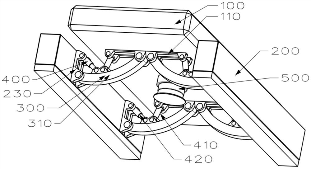
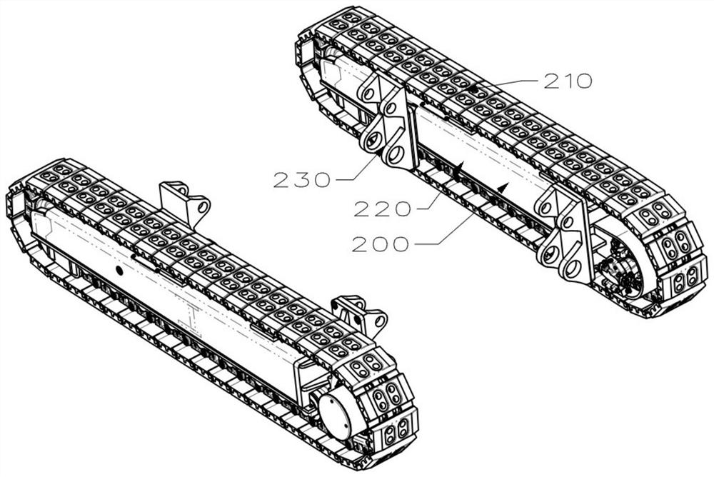
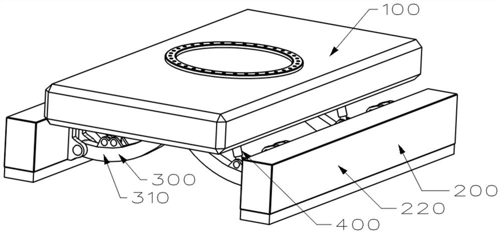
[0075] Such as Figure 1 to Figure 3 As shown, the high-passability hydraulic drilling rig of the present invention includes a chassis main body 100 , a crawler belt assembly 200 , a crawler track positioning plate set 300 , a positioning cylinder set 400 and a lifting support column 500 .

[0076] The chassis main body 100 plays the role of carrying the working parts of the drilling rig and connecting other parts of the chassis of the drilling rig. The structure of the chassis main body 100 can be a rectangular plate or a box structure; the chassis main body 100 includes a positioning assembly 110, The positioning assembly 110 includes a track positioning shoe group positioning assembly and a positioning oil cylinder group positioning assembly. The track positioning shoe group positioning assembly plays the role of hinged the track positioning shoe group 300 and the chassis main body 100, and the positioning oil cylinder group positioning assembly It plays the role of hingedl...

Embodiment 2

[0086] In order to further enhance the passability of the drilling rig and reduce its turning radius; this implementation adds a lifting wheel set 600 on the basis of Embodiment 1; as Figure 6 to Figure 8 As shown, the lifting wheel set 600 is composed of four lifting wheels, which are respectively the first lifting wheel 610, the second lifting wheel 620, the third lifting wheel 630 and the fourth lifting wheel 640; At the bottom of the chassis main body 100, they are symmetrically arranged in groups of two, and a set of lifting wheels corresponds to a lifting support column 500; the first lifting wheels 610 and the second lifting wheels 620 are positioned on the basis of the first lifting wheels The support column 510 is the center of the circle, and the third lift wheel 630 and the fourth lift wheel 640 are positioned on the circle with the second lift support column 520 as the center of the circle; Figure 7 and 8As shown, the traveling direction of the first lifting whe...

Embodiment 3

[0091] Considering that the hydraulic drilling rig sometimes needs short-distance lateral movement during the operation process, but the lateral movement of the existing technology is cumbersome, time-consuming and labor-intensive, and requires a large space (need to repeatedly move backwards and forwards to achieve lateral movement). For the above problems, this embodiment adds an elevator wheel rotation assembly 680 on the basis of the second embodiment, through which the elevator wheel rotation assembly 680 changes the direction of travel of the elevator wheel and then moves the entire road drilling rig; the structure of the elevator wheel rotation assembly 680 Can be a combination of motor and gear.

[0092] Such as Figure 9 As shown, during the operation of this implementation, the drilling rig operator changes the traveling direction of the four lifting wheels through the lifting wheel rotating assembly 680 according to actual needs, and then drives the lifting wheel se...


PUM


Abstract

The application discloses a high-passability hydraulic drilling rig, which includes a chassis main body, a crawler assembly, a crawler positioning plate group, a positioning cylinder group, and a lifting support column; The role of connecting other parts of the chassis of the drilling rig; the track assembly is the traveling device of the drilling rig, which includes four wheels and a belt and a track box beam; the track positioning plate group is a combination of multiple track positioning plate units One end of the track positioning plate unit is hinged to the track box beam, and the other end is hinged to the chassis main body; the positioning oil cylinder group plays a role in controlling the track positioning plate group and the described track positioning plate group through its own expansion and contraction. The angle between the main body of the chassis and the angle between the track positioning plate group and the track assembly; the lifting support column is positioned at the bottom of the main body of the chassis to play a role in changing the width of the drilling rig. The function of supporting the drilling rig.

Description

technical field [0001] The invention relates to the technical field of an excavation drilling rig, in particular to a high-passability hydraulic excavation drilling rig. Background technique [0002] Crawler-type hydraulic drilling rigs for mines are used for blasting holes in small roadways and tunnels in underground engineering fields such as coal mines, metal and non-metal mines, water conservancy projects, etc., so that drilling operations in the roadway can be mechanized instead of manual. [0003] When traveling in the roadway, the crawler hydraulic drilling rig uses the crawler as the walking component, and drives the crawler to rotate and turn through the crawler drive wheel; the chassis of the crawler hydraulic drilling rig plays the role of carrying the working parts of the drilling rig; the crawler hydraulic drilling rig The chassis of the road drilling rig includes a chassis main body, a crawler box beam and crawlers, and the crawler box beam is fixedly connected...

Claims


Application Information

Patent Timeline
Patent Type & Authority Patents(China)
IPC IPC(8): E21B7/02E21B15/00B62D55/10
CPCE21B7/02E21B15/00B62D55/10
Inventor 杜长亭王愁王庆元宫配金
Owner XUZHOU HUAFENG MEASUREMENT & CONTROL TECH
Why Eureka
Try Eureka