Ejector matched with high-depth combustion chamber and combustor of ignition structure

A combustion chamber and ejector technology, which is used in combustion ignition, gas fuel burners, burners, etc., can solve problems such as inability to be applied, serious drawbacks, restricting the development and progress of commercial kitchen burner technology, and reduce the probability of occurrence. , Fast and stable ignition, to avoid the effect of deflagration

Pending Publication Date: 2020-10-30
浙江惠厨节能科技有限公司
View PDF0 Cites 1 Cited by
  • Summary
  • Abstract
  • Description
  • Claims
  • Application Information

AI Technical Summary

Problems solved by technology

[0005] To sum up, the commercial kitchen burner is a structure composed of many structural components. Each structural component performs its own duties. There are some benefits or constraints, and in many cases it is even a win-win contradictory relationship in which one trades off and the other grows. When many technical development and design personnel develop and design commercial kitchen burners, they often have problems due to whistling. Many technical developers are like walking on a balance beam to choose and balance between the excellent fire distributor design scheme or ignition structure design scheme, such as the problem of oil and water sundries, space volume problem, etc. A little carelessness, which seems to be an excellent point Features may not be applied due to serious disadvantages, which makes technology developers feel regretful and helpless, and also seriously restricts the development and progress of commercial kitchen burner technology

Method used


Image

  • Ejector matched with high-depth combustion chamber and combustor of ignition structure
  • Ejector matched with high-depth combustion chamber and combustor of ignition structure
  • Ejector matched with high-depth combustion chamber and combustor of ignition structure

Examples


Embodiment Construction

[0017] The following will clearly and completely describe the technical solutions in the embodiments of the present invention in conjunction with the accompanying drawings in the embodiments of the present invention, but this does not constitute a limitation to the protection scope of the present invention.

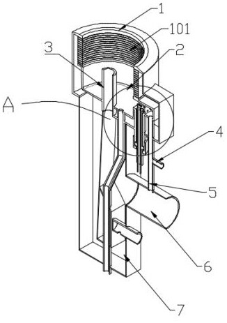
[0018] In the present invention, for a clearer description, the following description is made: the observer faces the attached figure 1 For observation, the left side of the observer is set as back, the right side of the observer is set as front, the front of the observer is set as left, the back of the observer is set as right, the top of the observer is set as up, and the bottom of the observer is set as down. It should be pointed out in the text The terms "front end", "rear end", "left side", "right side", "middle", "above", "below", etc. indicating the orientation or positional relationship are based on the orientation or positional relationship set in the drawings and...


PUM


Abstract

The invention relates to the technical field of commercial kitchen ware and in particular discloses an ejector matched with a high-depth combustion chamber and a combustor of an ignition structure, wherein an air ejection hose is arranged at the bottom of a distributor, an air flow ejected by the air ejection hose can dredge gas in the combustion chamber to flow out of the combustion chamber to reduce the probability of occurrence that the gas vibrates to induce squeal, and air ejected by the air ejection hose supplements air secondarily for combustion reaction of primary fire and mixed gas, so that the air flow of the fixed gas in the main fire can be reduced. A kindling material fire ejecting port is arranged in the inner side surface of an oil-water sundry reserving basin, so that the main fire and the mixed gas can be ignited quickly and stably to reduce the ignition time delay and avoid detonation generated by accumulation of the mixed gas. The ejector has independent tissue air and gas supplying and mixing and combusting functions and an independent kindling material mixed gas distribution chamber. An ignition needle function is not affected by a combustion flame in the distributor fully, so that the ejector has fully independent self-combustion and self-regulation function.

Description

technical field [0001] The invention relates to the technical field of commercial kitchen utensils, and specifically discloses a burner with an ejector and an ignition structure matched with a deep combustion chamber. Background technique [0002] The commercial kitchen burner with a cylindrical fire divider, its fire structure can be divided into a fire structure that supports diffusion combustion and a fire structure that supports premixed combustion according to the combustion method. Among them, the fire structure that supports premixed combustion is due to its Independent of the gas and air supply structure other than the mixed gas for the main fire, the combustion work of the mixed gas of the fire tissue will not be affected by the adjustment and switch of the main fire gas and air flow, so it can better protect the ignition needle electrode and the ignition needle electrode set inside the structure. The performance of the flameout protection detection electrode is sta...

Claims


Application Information

Patent Timeline
Patent Type & Authority Applications(China)
IPC IPC(8): F23D14/02F23D14/46F23D14/48F23D14/60F23D14/62F23Q3/00
CPCF23D14/02F23D14/46F23D14/48F23D14/60F23D14/62F23Q3/00
Inventor 李芳春陈惠良
Owner 浙江惠厨节能科技有限公司
Why Eureka
Try Eureka