Rice conveyor with grain moisture-proof function

A conveyor and rice technology, which is applied in the direction of drying machine, seed preservation through drying, filtering and sieving, etc., can solve the problems that rice cannot be dehumidified and dried, and achieve the effect of preventing excessive temperature, preventing moisture, and improving quality

Pending Publication Date: 2020-10-30
界首市金龙机械设备有限公司
7 Cites 0 Cited by

AI-Extracted Technical Summary

Problems solved by technology

[0003] The present invention mainly provides a rice conveyor with grain moisture-proof function to solve the technical prob...

Abstract

The invention provides a rice conveyor with a grain moisture-proof function. The rice conveyor with the grain moisture-proof function comprises a conveyor body, wherein a drying box is arranged at thetop of the conveyor body, a moisture-proof device is arranged on one side of the drying box, the moisture-proof device comprises a driving motor, a first driving wheel is arranged at the output end of the driving motor, a first threaded rod is arranged at the center of one side of the first driving wheel, one side of the first driving wheel is provided with a first driven wheel, a second threadedrod is arranged at the center of one side of the first driven wheel, a second driving wheel is arranged at one end of the second threaded rod, a second driven wheel is arranged at one side of the second driving wheel, a third threaded rod is arranged at the center of one side of the second driven wheel, moving blocks are arranged at one ends of the third threaded rod, the second threaded rod andthe first threaded rod respectively, and heating lamps are arranged at the bottom of the moving blocks. According to the rice conveyor with the grain moisture-proof function, the heating lamps are driven by the multiple threaded rods to uniformly dry and heat rice, so that the quality of the rice is improved.

Application Domain

Technology Topic

Image

  • Rice conveyor with grain moisture-proof function
  • Rice conveyor with grain moisture-proof function
  • Rice conveyor with grain moisture-proof function

Examples

  • Experimental program(1)

Example Embodiment

[0022] In order to facilitate the understanding of the present invention, the following will make a more comprehensive description of the present invention with reference to the relevant drawings. The drawings show several embodiments of the present invention, but the present invention can be implemented in different forms and is not limited to what is described in the text. On the contrary, these embodiments are provided to make the disclosure of the present invention more thorough and comprehensive.
[0023] It should be noted that when a component is referred to as being "fixed to" another component, it can be directly on the other component or there may be a centered component. When a component is considered to be "connected" to another component, it can be It is directly connected to another element or there may be a centered element at the same time. The terms "vertical", "horizontal", "left", "right" and similar expressions used herein are only for illustrative purposes.
[0024] Unless otherwise defined, all technical and scientific terms used herein have the same meaning as those commonly connected by those skilled in the technical field of the present invention. The term knowledge used in the description of the present invention herein is for describing specific embodiments. The purpose is not to limit the present invention. The term "and/or" used herein includes any and all combinations of one or more related listed items.
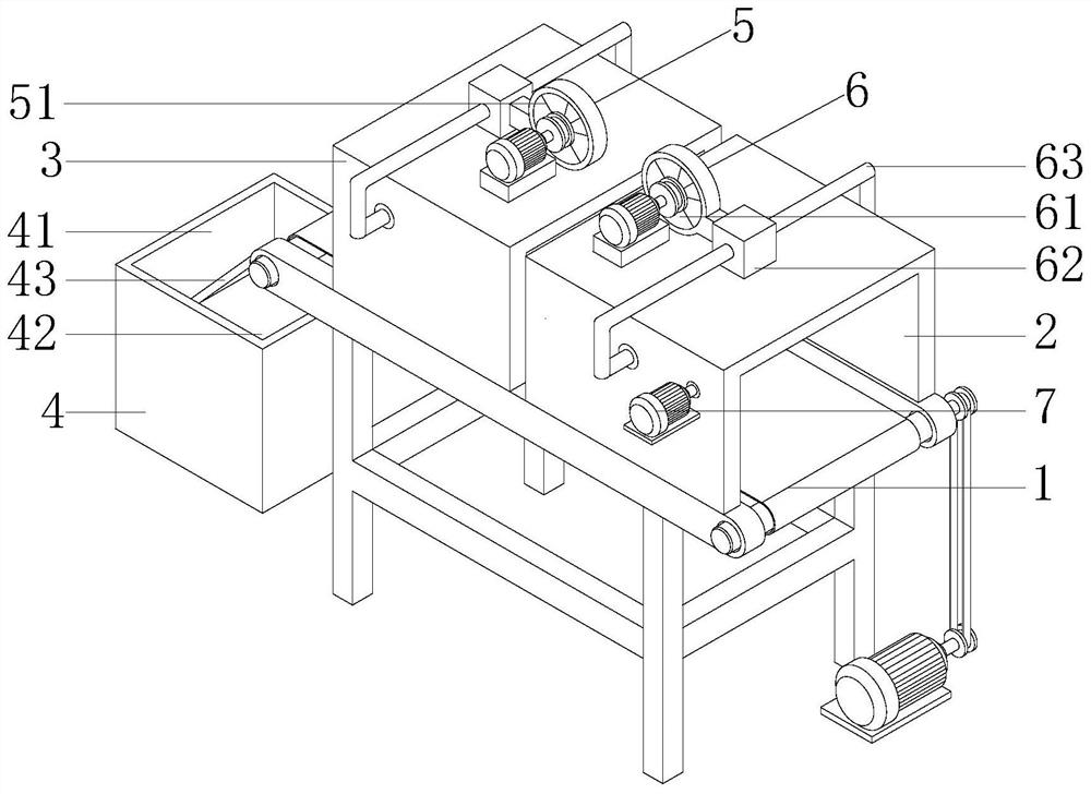
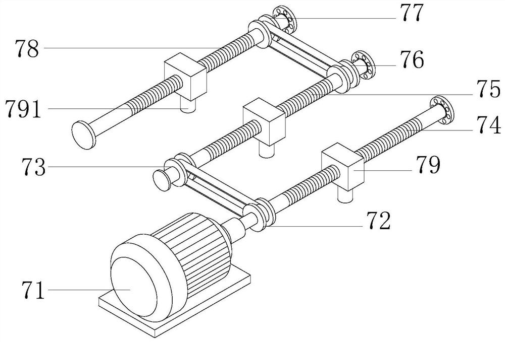
[0025] Please refer to the attached Figure 1-4 , A rice conveyor with grain moisture-proof function, comprising a conveyor body 1, the top two side baffles of the conveyor body 1 are fixed with a drying box 2 by bolts, and one side of the drying box 2 is provided with a moisture-proof Device 7, the moisture-proof device 7 includes a drive motor 71 that is fixed on a side support plate of the drying box 2 by bolts and arranged horizontally, and the output end of the drive motor 71 penetrates through the side shell of the drying box 2 Extending to the inside, a first driving wheel 72 is connected. A first threaded rod 74 penetrates through the center of the first driving wheel 72 away from the driving motor 71, and one side of the first driving wheel 72 passes The belt is rotatably connected with a first driven wheel 73, and a second threaded rod 75 penetrates through the center of the first driven wheel 73 away from the drive motor 71, and the second threaded rod 75 is away from the first driven wheel. One end of the driving wheel 73 is connected with a second driving wheel 76. The side of the second driving wheel 76 away from the first threaded rod 74 is rotatably connected to a second driven wheel 77 through a belt. The second driven wheel 77 is close to A third threaded rod 78 penetrates through the center of one side of the first driven wheel 73, and one end of the third threaded rod 78, the second threaded rod 75 and the first threaded rod 74 is penetrated and connected with a moving block 79, A heating lamp 791 is connected to the bottom of each moving block 79, and both ends of the third threaded rod 78, the second threaded rod 75 and the first threaded rod 74 extend to both sides of the drying box 2 The inner wall is rotatably connected by ball bearings.
[0026] Please refer to the attached figure 1 , The cooling box 3 is provided with a collection box 4 on the side away from the drying box 2, the collection box 4 is provided at the bottom of one end of the conveyor body 1, and the collection box 4 consists of a rice collection box 41 and impurities A collection box 42 is composed; the top of the partition between the rice collection box 41 and the impurity collection box 42 is fixed with a screen 43 by bolts, and the end of the screen 43 away from the collection box 4 and the conveyor body 1 One end of the bottom is connected and fixed. In this embodiment, through the design of the screening net 43, the rice can be effectively screened and separated from internal impurities for collection, thereby making the rice more pure.
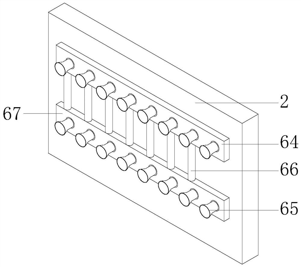
[0027] Please refer to the attached figure 1 with 3 , The top of the drying box 2 is provided with a drying device 6, the drying device 6 includes a first fan 61 fixed on the top surface of the drying box 2 by bolts, the output end of the first fan 61 passes through an air duct A heater 62 is connected. The two sides of the heater 62 are symmetrically connected with first heating pipes 63. The two first heating pipes 63 respectively penetrate through the shells on both sides of the drying box 2 and extend to the inside connected with the first heating pipes. Two heating tubes 64, the bottoms of the two second heating tubes 64 are each provided with a third heating tube 67, each of the third heating tube 67 and the second heating tube 64 are fixed to the drying box 2 by bolts On the inner wall; the top ends of the two third heating tubes 67 and the bottom ends of the two second heating tubes 64 are connected with a plurality of connecting tubes 66 at equal intervals, and the two third heating tubes 67 A plurality of first air jet nozzles 65 are connected to the side of the second heating tube 64 far away from the inner wall of the drying box 2 at even intervals. In this embodiment, by starting the heater 62 and the first fan 61 to work, the first fan 61 delivers the outside air to the heater 62 for heating, and then delivers it to the second heating tube 64 and the second heating tube 64 through the two first heating tubes 63. In the third heating tube 67, the first air nozzles 65 can be sprayed to dry and heat the rice to prevent the rice from being damp.
[0028] Please refer to the attached figure 1 with 4 , One side of the drying box 2 is provided with a cooling box 3, the cooling box 3 is fixed by bolts on the two side baffles of the top of the conveyor body 1, and the top of the cooling box 3 is provided with a cooling device 5 The cooling device 5 includes a second fan 51 fixed on the top surface of the cooling box 3 by bolts. The output end of the second fan 51 is connected to a condenser 52 through an air duct. A first cooling pipe 53 is connected to the side symmetrically, and the two first cooling pipes 53 respectively penetrate through the two side shells of the cooling box 3 and extend to the inside connected with a second cooling pipe 54. The two second cooling pipes The side of 54 away from the inner wall of the cooling box 3 is connected with a plurality of second air jet nozzles 55 at equal intervals. In this embodiment, by starting the condenser 52 and the second fan 51 to work, the second fan 51 delivers the outside air to the condenser 52 to cool down and then deliver it to the second cooling pipe 54 through the two first cooling pipes 53 Inside, the rice can be sprayed through a plurality of second air nozzles 55 to cool the rice, so as to prevent the subsequent staff from being scalded during the collection due to the excessive temperature in the drying box 2.
[0029] The specific operation mode of the present invention is as follows:
[0030] When the present invention needs to be used, the rice is first put on the conveyor belt of the conveyor body 1, and the movement of the conveyor belt is started. When the rice is transported to the drying box 2, the heater 62 and the first fan 61 are first started to work. The fan 61 transports outside air to the heater 62 for heating, and then transports it to the second heating pipe 64 and the third heating pipe 67 through the two first heating pipes 63, and then sprays it through the multiple first air nozzles 65, Dry heat treatment of rice;
[0031] Then the drive motor 71 is started to work, the first driving wheel 72 drives the first driven wheel 73 to rotate through the belt, the first driven wheel 73 drives the second threaded rod 75 to rotate, the second threaded rod 75 drives the second driving wheel 76 to rotate, and the second The driving wheel 76 drives the second driven wheel 77 to rotate through a belt, while the first driving wheel 72 and the second driven wheel 77 respectively drive the first threaded rod 74 and the third threaded rod 78 to rotate, so that the moving block 79 can drive the heating lamp 791 Move back and forth to dry and heat the rice;
[0032] When the rice is transported to the cooling box 3, the condenser 52 and the second fan 51 are started to work. The second fan 51 delivers the outside air to the condenser 52 for cooling, and then transports it to the second through the two first cooling pipes 53 In the cooling pipe 54, it is finally sprayed out through a plurality of second air nozzles 55 to cool the rice, and finally the rice is screened and separated along the screen 43 to separate the rice and impurities and fall into the rice collection box 41 and the impurities collection box 42 for collection. .
[0033] Although the embodiments of the present invention have been shown and described, those of ordinary skill in the art can understand that various changes, modifications, and substitutions can be made to these embodiments without departing from the principle and spirit of the present invention. And variants, the scope of the present invention is defined by the appended claims and their equivalents. Therefore, the embodiments of the present invention are only an illustrative example for the present invention, and the embodiments of the present invention do not constitute an impact on the present invention from any point of view. limit.

PUM

no PUM

Description & Claims & Application Information

We can also present the details of the Description, Claims and Application information to help users get a comprehensive understanding of the technical details of the patent, such as background art, summary of invention, brief description of drawings, description of embodiments, and other original content. On the other hand, users can also determine the specific scope of protection of the technology through the list of claims; as well as understand the changes in the life cycle of the technology with the presentation of the patent timeline. Login to view more.

Similar technology patents

Method for preparing silicone hydrogels

ActiveUS20070132949A1Quality improvementReduced polymerization shrinkageOptical articlesCeramic shaping apparatusSilicone hydrogelLow modulus
Owner:ALCON INC

Classification and recommendation of technical efficacy words

  • Quality improvement
  • Prevent moisture

Monodisperse core/shell and other complex structured nanocrystals and methods of preparing the same

ActiveUS20050129947A1Narrow size distributionQuality improvementMaterial nanotechnologyFrom normal temperature solutionsChemistrySemiconductor nanostructures
Owner:THE BOARD OF TRUSTEES OF THE UNIV OF ARKANSAS

Electronic paper apparatus

InactiveUS20080062506A1Prevent moistureEnhanced moisture resistanceNon-linear opticsOptical elementsClosed spaceElectronic paper
Owner:GIGNO TECH CO LTD

Continuous, quantitative and rotary feeder

InactiveCN106629126APrevent moisture from entering the material binPrevent moistureLoading/unloadingEngineeringMoisture
Owner:吴云萍
Why Eureka
Try Eureka