
Curing furnace for ceramic capacitor production

A technology of ceramic capacitors and curing furnaces, applied in the field of capacitors, can solve the problems of long curing time of capacitors, increased difficulty of operation for staff, and difficulty in taking them out.

Inactive Publication Date: 2020-10-30
NINGGUO HUILI ELECTRIC APPLIANCE
View PDF7 Cites 0 Cited by
  • Summary
  • Abstract
  • Description
  • Claims
  • Application Information

AI Technical Summary

Problems solved by technology

[0004] 1. When heating the existing curing furnace, because the ceramic capacitor has a certain amount of moisture during heating, the heating effect is slow, and the heat is not easily distributed and wrapped inside the device, which increases the waiting time of the operator and delays the subsequent work efficiency;
[0005] 2. During the heating process of the device, the heat dissipates faster, and the heat preservation effect is not easy to cure. Keep;
[0006] 3. After the capacitor is solidified, due to the high temperature in the device, it is difficult for the operator to take it out, which increases the difficulty of operation for the staff and reduces the functionality and practicability of the device.

Method used


Image

  • Curing furnace for ceramic capacitor production
  • Curing furnace for ceramic capacitor production
  • Curing furnace for ceramic capacitor production

Examples


Embodiment Construction

[0023] The following will clearly and completely describe the technical solutions in the embodiments of the present invention with reference to the accompanying drawings in the embodiments of the present invention. Obviously, the described embodiments are only some, not all, embodiments of the present invention. Based on the embodiments of the present invention, all other embodiments obtained by persons of ordinary skill in the art without making creative efforts belong to the protection scope of the present invention.

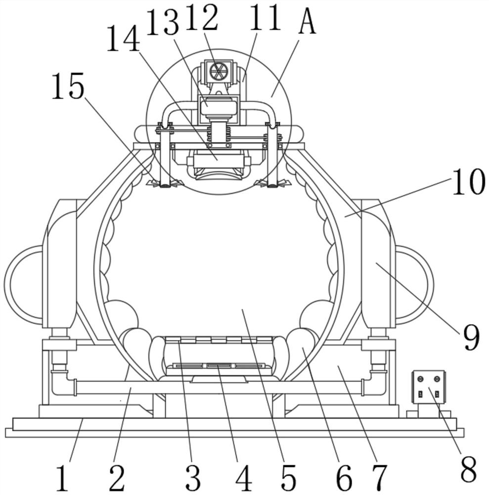
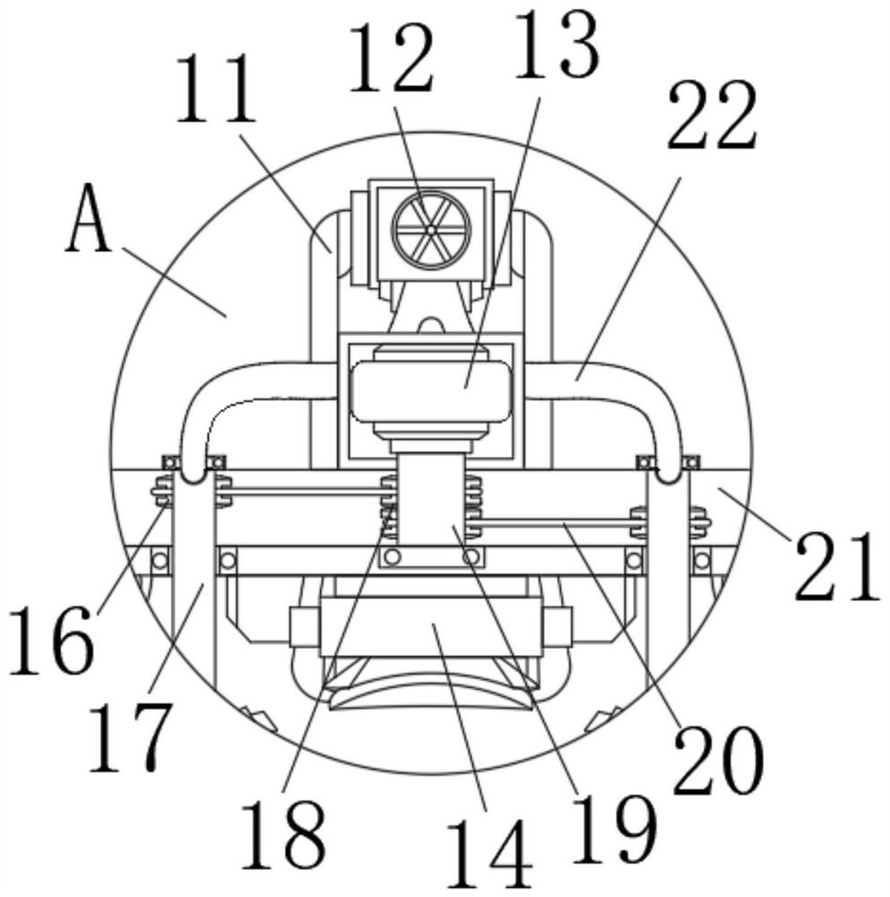
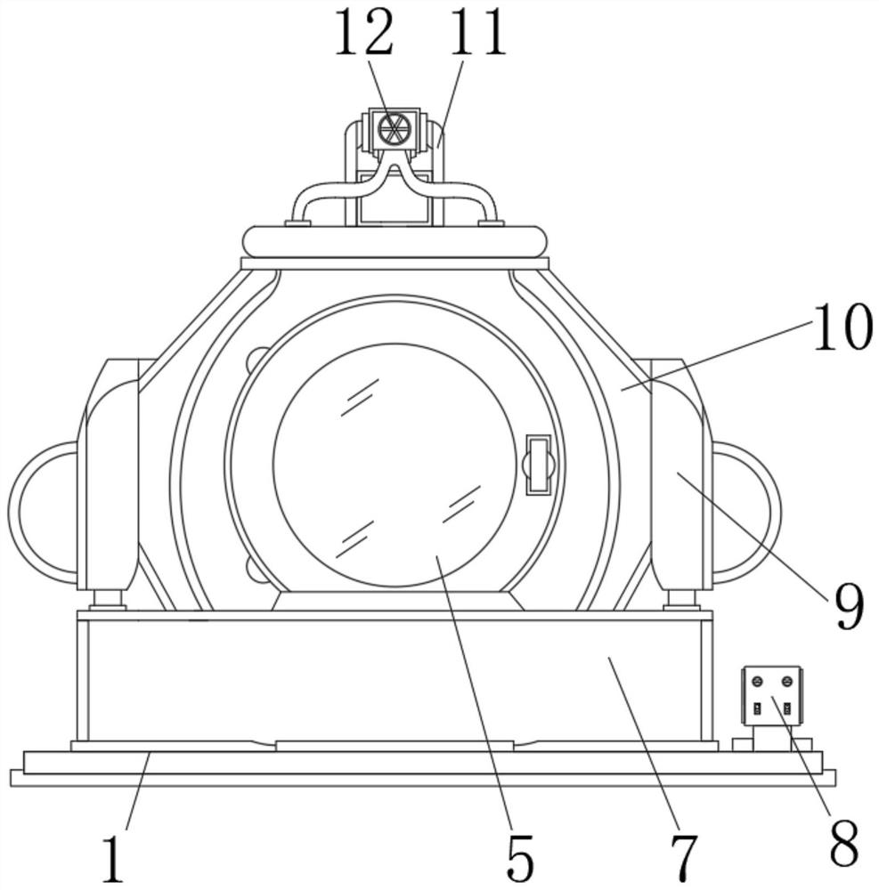
[0024] see Figure 1-4 , an embodiment provided by the present invention: a curing furnace for the production of ceramic capacitors, including a base 1, a curing furnace 5 is provided at the middle of the top of the base 1, and a sealing groove 7 is provided on the outside of the top of the base 1 near the curing furnace 5 , the both sides of curing oven 5 are provided with the heat shield 10 that cooperates with it, the both sides of heat shield 10 are provid...


PUM


Abstract

The invention discloses a curing furnace for ceramic capacitor production. The curing furnace for ceramic capacitor production comprises a base. A curing furnace body is arranged in the middle of thetop of the base. A sealing groove is formed in the portion, close to the outer side of the curing furnace body, of the top of the base. Thermal insulation plates which cooperate with the curing furnace body are arranged on the two sides of the curing furnace body, air guide grooves which communicate with the thermal insulation plates are formed in the two corresponding sides of the thermal insulation plates, and an air guide pipe is arranged at the bottoms of the air guide grooves. A permeable layer is arranged at the bottom of the interior of the curing furnace body. According to the curing furnace for ceramic capacitor production, a ceramic capacitor is placed through installation of a filtering screen frame, the start of a servo motor is utilized to drive sleeves and fan blades to rotate, a heat source, emitting the heat, of a heating mechanism is subjected to mixing turbulence, the storage efficiency of the heat source in the curing furnace body is improved, and the waiting time ofan operator is shortened. Meanwhile, the moisture of the capacitor is filtered to flow away under the condition that the filtering screen frame is installed and conducts filtering operation, the capacitor can be quickly heated, and the curing working efficiency can be improved.

Description

technical field [0001] The invention relates to the technical field of capacitors, in particular to a curing furnace for producing ceramic capacitors. Background technique [0002] Ceramic capacitors are a general term for capacitors with ceramic materials as the medium. Ceramic capacitors need to be baked in production to remove moisture. The most common drying equipment is an internal circulation single-box curing furnace. It first puts the baked capacitors into the curing furnace, Next, first heat the to-be-baked material in the box, when the temperature in the box reaches the requirement, vacuumize the box to remove moisture under the condition of heat preservation, and then heat the to-be-baked substance in the box when the moisture in the capacitor meets the requirement The baked capacitor is naturally cooled or forced to cool, and after the temperature of the baked capacitor is reduced to a certain level, the baked capacitor is taken out and sealed for storage; [0...

Claims


Application Information

Patent Timeline
Patent Type & Authority Applications(China)
IPC IPC(8): F27D1/10F27D1/18F27D5/00F27D9/00F27D17/00F27D21/02
CPCF27D5/00F27D17/008F27D9/00F27D1/1858F27D1/10F27D21/02F27D2009/0005Y02P10/25
Inventor 叶麒麟
Owner NINGGUO HUILI ELECTRIC APPLIANCE
Learn More