Resistive memory and its drive control circuit

A technology for driving control circuits and resistive memory, which is applied in the field of storage, can solve the problems that the area of ​​resistive memory cannot be reduced, the proportion of resistive memory cell array is large, and the occupied area is large, so as to reduce the occupied area and facilitate miniaturization. to achieve the effect of the overall area

Active Publication Date: 2022-07-19
XIAMEN IND TECH RES INST CO LTD
View PDF0 Cites 0 Cited by
  • Summary
  • Abstract
  • Description
  • Claims
  • Application Information

AI Technical Summary

Problems solved by technology

[0003] However, devices with higher withstand voltage relatively require a larger occupied area, and with the continuous development of semiconductor storage technology, the area of ​​the resistive memory unit RRAM cell will continue to shrink, which leads to the Y Select part and SET When the PMOS / NMOS in the / RESET driving part is a high-voltage device and cannot be scaled down, the proportion of the resistive memory cell array is getting larger and larger, especially each bit line BL needs a set of Y select and SET / RESET When the driver cannot shrink the area synchronously with the RRAM cell, the area of ​​the resistive memory cannot be reduced

Method used


Image

  • Resistive memory and its drive control circuit
  • Resistive memory and its drive control circuit
  • Resistive memory and its drive control circuit

Examples


Embodiment Construction

[0027] The following describes in detail the embodiments of the present invention, examples of which are illustrated in the accompanying drawings, wherein the same or similar reference numerals refer to the same or similar elements or elements having the same or similar functions throughout. The embodiments described below with reference to the accompanying drawings are exemplary, and are intended to explain the present invention and should not be construed as limiting the present invention.

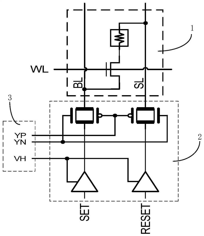
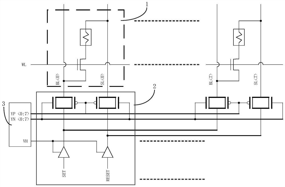
[0028] In the resistive memory and its drive control circuit of the embodiment of the present invention, the high-voltage transmission gate unit with high voltage resistance is used to provide the high-voltage power supply and the sampling isolation high-voltage unit is used to resist the high-voltage power supply, so that most circuits that originally need to use high-voltage devices can be replaced by most of them. The area of ​​low-voltage devices with a small area can be greatly reduc...


PUM


Abstract

The invention discloses a drive control circuit of a resistive memory, comprising: a low-voltage drive control unit, the low-voltage drive control unit generates a low-voltage drive signal according to a write signal; a high-voltage transmission gate unit, the high-voltage transmission gate unit It is assumed that the high voltage provided by the power supply applies the low voltage driving signal to the corresponding resistive memory cell in the resistive memory, so as to perform a writing operation on the resistive memory cell. The driving control circuit of the embodiment of the present invention uses low-voltage devices and low-voltage signals to realize low-voltage driving, thereby greatly reducing the occupied area of ​​the SET / RESET driving part and realizing the reduction of the overall area of ​​the resistive memory. The invention also discloses a resistive memory with the driving control circuit.

Description

technical field [0001] The present invention relates to the technical field of storage, in particular to a drive control circuit of a resistive memory and a resistive memory having the drive control circuit. Background technique [0002] In related technologies, such as figure 1 and figure 2 As shown, the bipolar resistive memory includes a plurality of resistive memory cells 1, each resistive memory cell according to image 3 When operating according to the table shown, the SET / RESET driver section 2 and the Y select section 3 must use devices with high withstand voltage. [0003] However, devices with higher withstand voltages require a relatively large occupied area, and with the continuous development of semiconductor storage technology, the area of ​​the resistive memory cell RRAM cell will continue to shrink, which leads to the Y Select part and SET When the PMOS / NMOS of the / RESET drive part is a high-voltage device and cannot be scaled, the proportion of the resi...

Claims


Application Information

Patent Timeline
Patent Type & Authority Patents(China)
IPC IPC(8): G11C13/00
CPCG11C13/0069G11C13/0028G11C13/0026
Inventor 黄天辉陈瑞隆王丹云刘美冬
Owner XIAMEN IND TECH RES INST CO LTD
Why Eureka
Try Eureka