Four-switch single-phase single-stage switch boost inverter

A switching boost and inverter technology, which is applied in the direction of converting AC power input to DC power output, output power conversion devices, electrical components, etc. And the problems of reliability decline, weight, volume and cost increase, to achieve the effect of simple structure, convenient control, and reduce the number of use

Active Publication Date: 2020-10-30
NANJING UNIV OF AERONAUTICS & ASTRONAUTICS
View PDF5 Cites 6 Cited by
  • Summary
  • Abstract
  • Description
  • Claims
  • Application Information

AI Technical Summary

Problems solved by technology

[0002] In new energy power generation systems such as photovoltaic power generation and fuel cells, due to the low DC voltage provided by a single solar cell and fuel cell, it cannot meet the electricity demand of existing electrical equipment. Wide Gain Converter for Voltage
The traditional method is to use multiple Boost converters to cascade to boost the voltage. This method is expensive and uses a large number of devices, which will cause a decrease in system stability and reliability; the second is to introduce a Z source between the input source and the load. Impedance network, through the cascading of multi-level quasi-Z source impedance network can output very high voltage gain, however, the cascading of multiple quasi-Z source units increases the number of passive components such as inductors and capacitors in the circuit topology, making The weight, volume, and cost of the system are greatly increased, which limits the application of the circuit in low-power circuits that are limited by system cost, weight, and volume.

Method used


Image

  • Four-switch single-phase single-stage switch boost inverter
  • Four-switch single-phase single-stage switch boost inverter
  • Four-switch single-phase single-stage switch boost inverter

Examples


Embodiment Construction

[0014] The technical solution of the invention will be described in detail below in conjunction with the accompanying drawings.

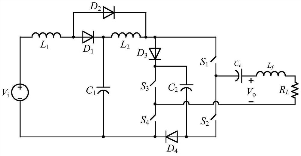
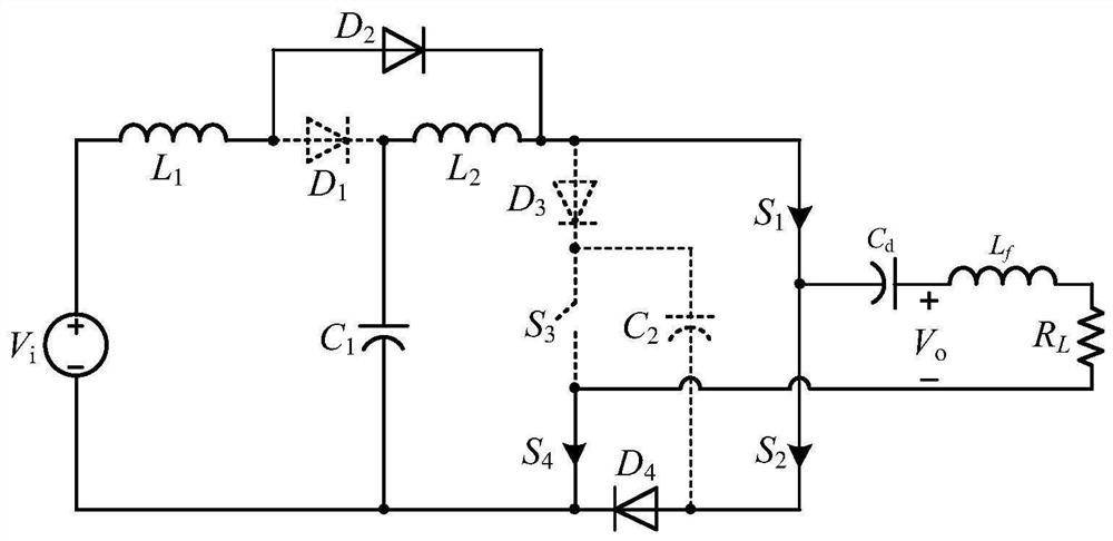
[0015] refer to figure 1 , the four-switch single-phase single-stage switching boost inverter circuit disclosed by the present invention, which includes: a first inductor L 1 , the first diode D 1 , the first capacitance C 1 and the second diode D 2 Composed of the first stage boost circuit, the second inductor L 2 , the second capacitance C 2 , the third diode D 3 , the fourth diode D 4 And the second step-up circuit composed of the inverter bridge, the filter capacitor C d , load R L and filter inductor L f The output circuit composed of, wherein, the inverter bridge is composed of the first switching tube S 1 , the second switch tube S 2 , the third switch tube S 3 and the fourth switch S 4 tube composition.

[0016] figure 1 The connection relationship of each device in the shown four-switch single-phase single-stage switching boo...


PUM


Abstract

The invention discloses a four-switch single-phase single-stage switch boost inverter circuit, and belongs to the technical field of power generation, power transformation or power distribution. The circuit comprises a first boosted circuit composed of a first inductor, a first diode, a first capacitor and a second diode, a second boosted circuit composed of a second inductor, a second capacitor,a third diode, a fourth diode and an inverter bridge, and an output circuit composed of a filter capacitor and a load. The whole circuit structure is simple, the power supply input current is continuous, the single-stage buck-boost characteristics of a switch inductor-capacitor unit and a quasi-switch boost network are combined, the higher output voltage gain is achieved, the load current is continuous, direct connection and open circuit immunity are achieved, the circuit can work in a direct connection state, and starting impulse current and impulse current at the moment when a switch tube isturned on do not exist in the circuit.

Description

technical field [0001] The invention relates to power electronic circuit technology, in particular to a four-switch single-phase single-stage switching boost inverter, which belongs to the technical field of power generation, transformation or distribution. Background technique [0002] In new energy power generation systems such as photovoltaic power generation and fuel cells, due to the low DC voltage provided by a single solar cell and fuel cell, it cannot meet the electricity demand of existing electrical equipment. voltage wide-gain converter. The traditional method is to use multiple Boost converters to cascade to boost the voltage. This method is expensive and uses a large number of devices, which will cause a decrease in system stability and reliability; the second is to introduce a Z source between the input source and the load. Impedance network, through the cascading of multi-level quasi-Z source impedance network can output very high voltage gain, however, the c...

Claims


Application Information

Patent Timeline
Patent Type & Authority Applications(China)
IPC IPC(8): H02M7/5387H02M1/12
CPCH02M1/126H02M7/5387
Inventor 朱小全陈致君金科
Owner NANJING UNIV OF AERONAUTICS & ASTRONAUTICS
Why Eureka
Try Eureka