
Receiving device positioning method, device and system, storage medium and electronic device

A technology of a receiving device and a positioning method, which is applied in the field of communication and can solve problems such as inability to locate an electromagnetic reflecting surface.

Pending Publication Date: 2020-10-30
ZTE CORP
View PDF0 Cites 14 Cited by
  • Summary
  • Abstract
  • Description
  • Claims
  • Application Information

AI Technical Summary

Problems solved by technology

[0005] The embodiment of the present application provides a positioning method and device, system, storage medium and electronic device for a receiving device, so as to at least solve the technical problem in the related art that the terminal cannot be positioned by using the characteristics of the electromagnetic reflective surface itself

Method used


Image

  • Receiving device positioning method, device and system, storage medium and electronic device
  • Receiving device positioning method, device and system, storage medium and electronic device
  • Receiving device positioning method, device and system, storage medium and electronic device

Examples


Embodiment Construction

[0041] Embodiments of the present application will be described in detail below with reference to the drawings and in combination with the embodiments.

[0042] It should be noted that the terms "first" and "second" in the description and claims of the present application and the above drawings are used to distinguish similar objects, but not necessarily used to describe a specific sequence or sequence.

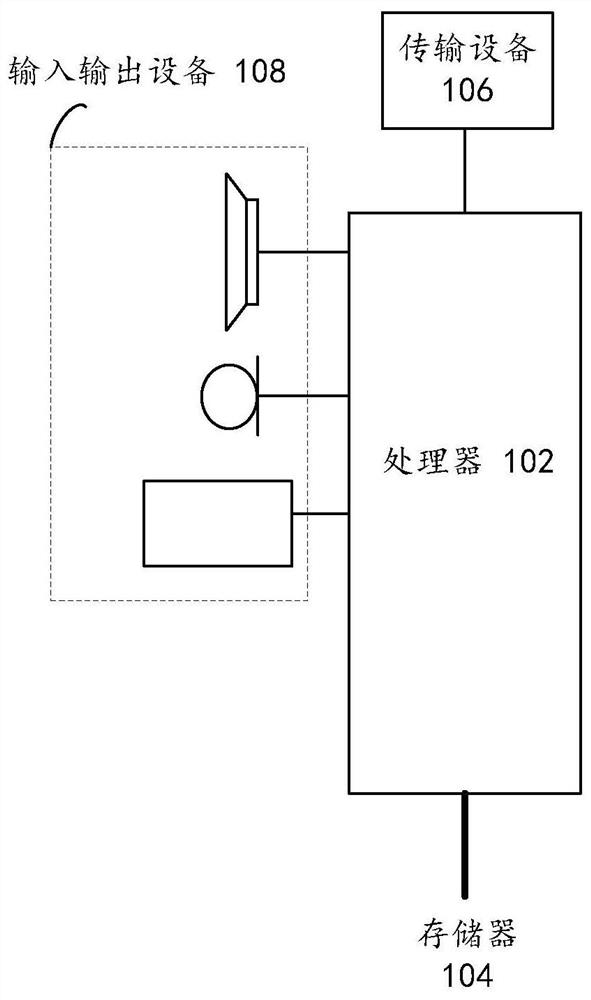
[0043] The method embodiments provided in the embodiments of the present application may be executed in mobile terminals, computer terminals or similar computing devices. Taking running on an electronic device as an example, figure 1 It is a block diagram of the hardware structure of the electronic device according to the positioning method of the receiving device according to the embodiment of the present application. Such as figure 1 As shown, the electronic device may include one or more ( figure 1 Only one is shown in the figure) a processor 102 (the processor 102 may ...


PUM


Abstract

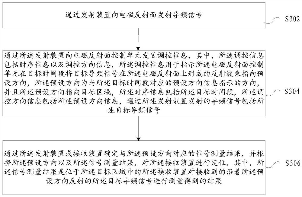
The embodiment of the invention provides a positioning method, device and system of a receiving device, a storage medium and an electronic device. The method comprises the following steps of transmitting a pilot signal to an electromagnetic reflecting surface through a transmitting device; regulation and control information being sent to the electromagnetic reflecting surface control unit throughthe transmitting device; wherein the regulation and control information comprises the time sequence information and regulation and the control direction information, the regulation and control information being used for indicating the electromagnetic reflection surface control unit to point a reflection wave beam formed by the target pilot signal on the electromagnetic reflection surface to a preset direction in a target time period, and the preset direction being a direction indicated by preset direction information corresponding to the target time period; and determining a signal measurementresult corresponding to the preset direction through the transmitting device or the receiving device, and positioning the receiving device according to the preset direction and the signal measurementresult. According to the method, a technical problem that the terminal cannot be positioned by utilizing the characteristics of the electromagnetic reflecting surface in the prior art is solved, andthe effect of positioning the terminal by utilizing the characteristics of the electromagnetic reflecting surface is achieved.

Description

technical field [0001] The embodiments of the present application relate to the communication field, and in particular, relate to a positioning method and device, system, storage medium, and electronic device for a receiving device. Background technique [0002] The direction of arrival (Direction of Arrival, referred to as DOA) estimation method of the traditional array beam includes multiple signal classification (Multiple Signal Classification, referred to as MUSIC), rotation invariant subspace (Estimating Signal parameter via Rotation Invariance Techniques, referred to as ESPRIT) and other methods are based on the fact that the array elements have independent measurement functions (such as measuring incoming wave phase). However, for smart electromagnetic reflective surfaces (also known as smart reflective surfaces, electromagnetic reflective surfaces), the addition of this measurement function will reduce reflection efficiency and increase costs, so smart reflective sur...

Claims


Application Information

Patent Timeline
Patent Type & Authority Applications(China)
IPC IPC(8): H04W4/021H04W4/02H04L5/00H04W16/28
CPCH04W4/021H04W4/02H04W4/026H04L5/0048H04W16/28G01S13/89G01S13/426G01S2013/464G01S13/46G01S7/024H04L5/0053H04L5/0091H04W64/00H04B7/15528H04B7/04013G01S13/48G01S7/03G01S13/876
Inventor 窦建武方敏陈艺戬张楠彭琳
Owner ZTE CORP
Learn More