

Multidirectional feed trough device for livestock breeding feeding
A feeding trough and feed trough technology, applied in animal feeding devices, animal husbandry, applications, etc., can solve problems such as unfavorable animal breeding, animal injury, and mutual competition for food, so as to reduce mutual competition, reduce the occurrence of food competition, Conducive to the effect of animal growth and breeding
- Summary
- Abstract
- Description
- Claims
- Application Information
AI Technical Summary
Problems solved by technology
Method used
Image

Examples
Embodiment 1
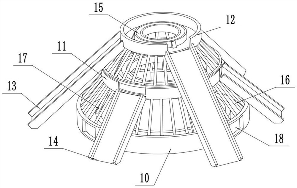
[0020] see Figure 1-3 , a multi-directional feeding trough device for animal husbandry and breeding, comprising a feed trough 15 and a base 27; the bottom of the base 27 is fixedly installed in the middle of the livestock farm through multiple groups of annularly arranged anchor bolts 26, so that animals on all sides can be nearby eat. The bottom of the anchor bolt 26 is a tapered structure, which is convenient for inserting into the soil stably and quickly. The top of described base 27 is fixedly installed with the bottom groove 10 of a group of annular structures, and bottom groove 10 is provided with concentric middle groove 11 and top groove 12 successively, bottom groove 10, middle groove 11, top groove The diameter of 12 decreases successively to facilitate the stable placement of the whole device. The bottom groove 10 , the middle groove 11 , and the inner side tops of the top groove 12 are fixedly supported and connected by three groups of inclined support rods 17 ....
Embodiment 2
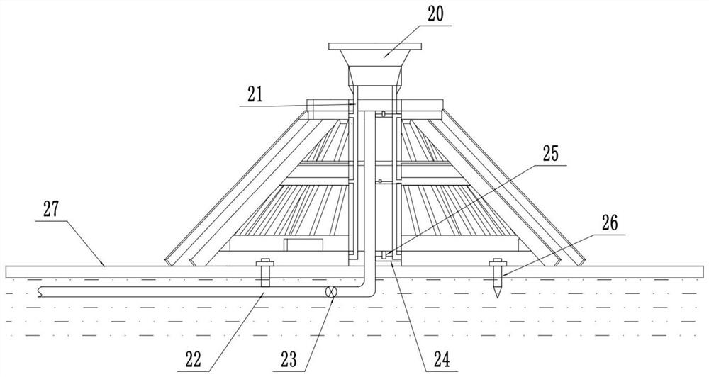
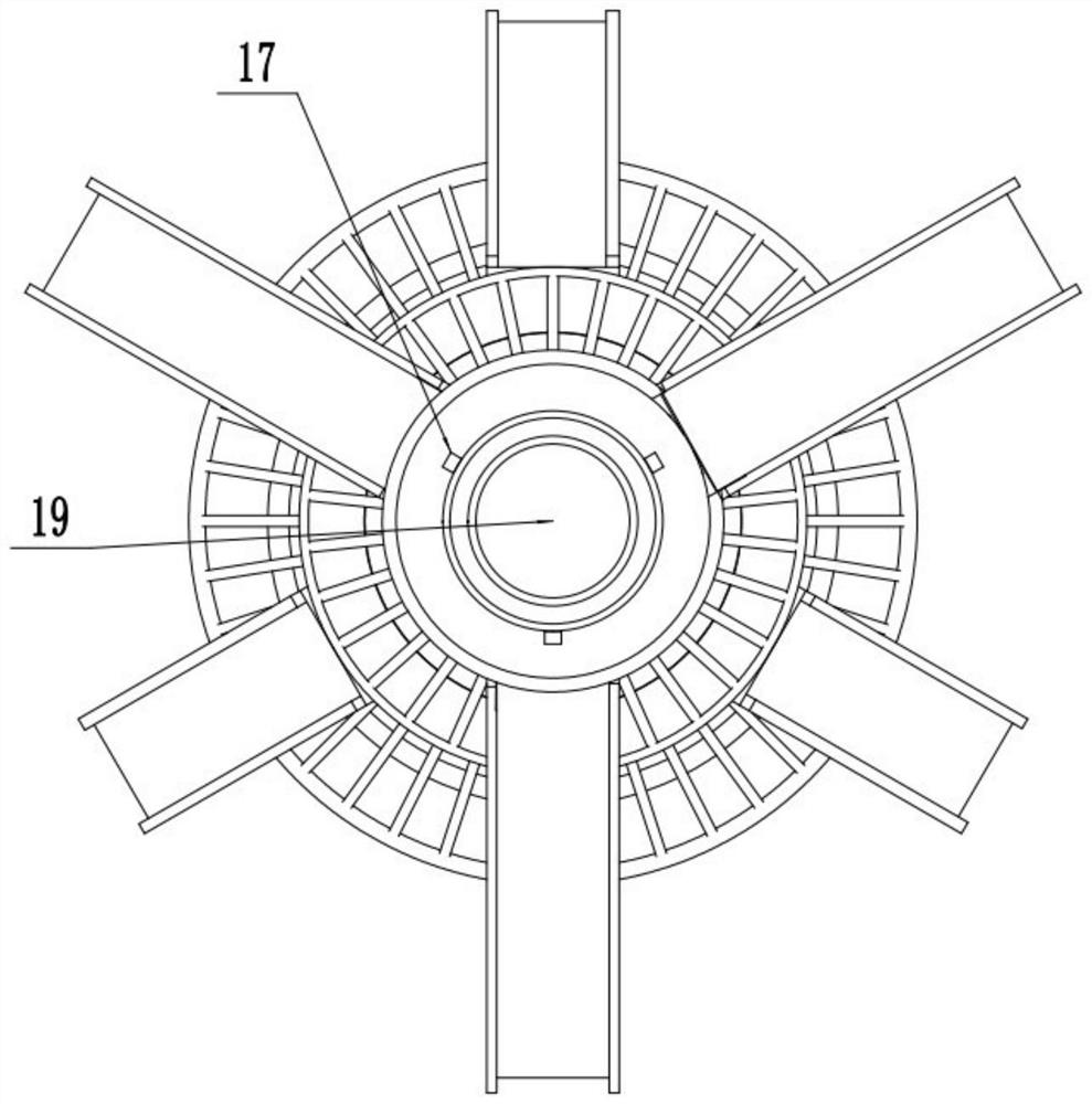
[0022] On the basis of Embodiment 1, a set of middle cavity 19 with an upper opening is provided in the middle of the bottom tank 10, middle tank 11, and top tank 12, and the top of the middle cavity 19 communicates upward with a material storage chamber 20 with a trumpet-shaped structure. , the feed to be used is conveniently stored temporarily through the storage chamber 20 . The bottom of the storage chamber 20 is connected downwards with multiple groups of feeding pipes 21, and the feeding pipes 21 are respectively connected with feeding pipes extending to the inside of the feed tank 15, and the feeding pipes 21 are provided with electric control valves. The feeding pipe 21 controls the feed supply inside the feed trough 15, thereby facilitating the staff to remotely control the addition of the feed.
[0023] The inner middle part of the cavity 19 is provided with a group of vertical water delivery pipes 22, the bottom of the water delivery pipes 22 extends into the soil a...
PUM
 Abstract
Description
Claims
Application Information