Bolt model automatic detection device and control method

A technology of automatic detection device and control method, applied in sorting and other directions, can solve the problems of product scrapping cost loss, unstable detection effect, backward detection technology, etc., to reduce after-sales service costs, strong visual capture effect, and visual capture effect. Good results

Pending Publication Date: 2020-11-03
GREE ELECTRICAL APPLIANCE WUHU +1
View PDF7 Cites 3 Cited by
  • Summary
  • Abstract
  • Description
  • Claims
  • Application Information

AI Technical Summary

Problems solved by technology

At present, most production factories use relatively primitive manual detection methods. The detection technology is backward, and the detection effect is unstable and prone to misuse and mixed use, which directly leads to the failure of assembly of parts and the loss of product scrap costs.

Method used


Image

  • Bolt model automatic detection device and control method
  • Bolt model automatic detection device and control method
  • Bolt model automatic detection device and control method

Examples


Embodiment 1

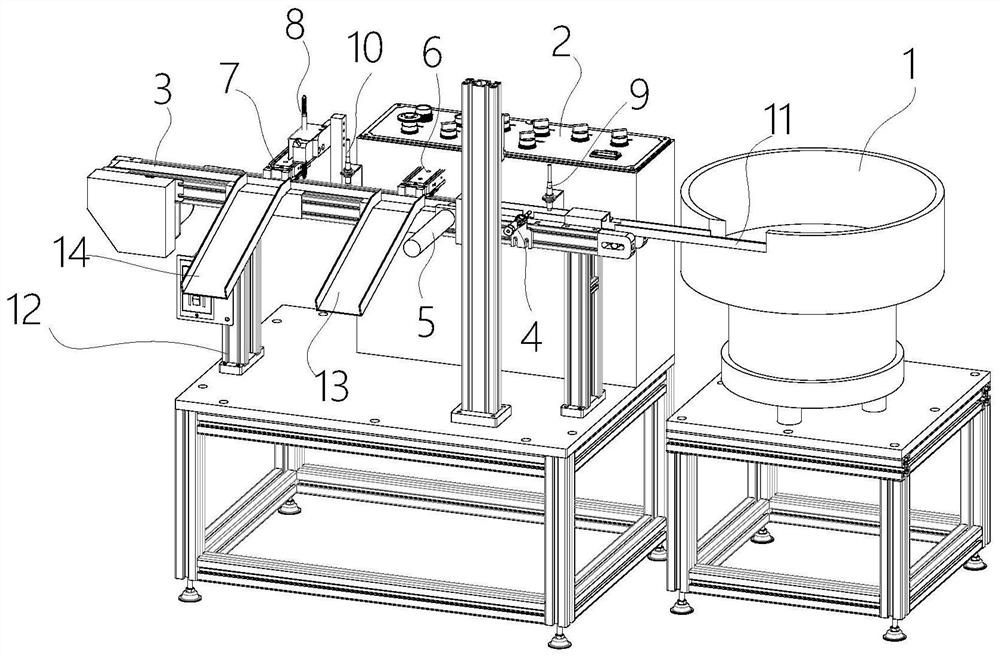
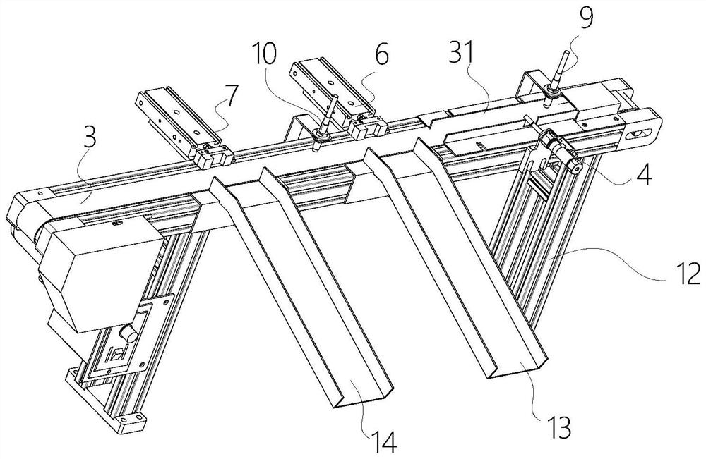
[0045] In view of the current use of the original manual detection method to distinguish bolts of different specifications, the detection technology is backward, the detection effect is unstable and prone to misuse and mixed use, which directly leads to the problem that the parts cannot be assembled and the cost of product scrapping is lost. This embodiment proposes An automatic detection device for bolt type, such as Figure 1-Figure 3As shown, including: bolt transmission device, visual inspection system and bolt pushing mechanism.

[0046] The bolt transmission device sequentially transports the bolts through the belt line 3 ; specifically, the bolt transmission device includes a support frame 12 on which the belt line 3 is arranged. Preferably, the bolt transmission device further includes a vibrating plate 1 , and the vibrating plate 1 arranges the bolts in an orderly orientation through vibration before outputting them. The output end of the vibration plate 1 is provide...

Embodiment 2

[0062] This embodiment discloses the control method of the bolt type automatic detection device of the embodiment. The control method includes: when the visual detection device collects the image information of the bolts conveyed by the belt line, and distinguishes the qualified products from the non-qualified bolts according to the image information , the control bolt pushing mechanism pushes qualified products and / or non-qualified products out of the belt line.

[0063] Further optionally when the pushing mechanism includes a first pushing cylinder, the control method includes:

[0064] When the bolts are conveyed sequentially on the belt line, the visual inspection system is controlled to collect the image information of the bolts conveyed by the belt line, and the qualified and non-qualified bolts are distinguished according to the image information;

[0065] Control the first push cylinder to push qualified or non-qualified products out of the conveyor.

[0066] Further ...


PUM


Abstract

The invention discloses a bolt model automatic detection device and a control method. The bolt model automatic detection device comprises a bolt conveying device, a visual detection system and a boltpushing mechanism; the bolt conveying device sequentially conveys bolts through a belt line; the visual detection system is used for collecting image information of the bolts conveyed by the belt lineand distinguishing qualified products from unqualified products of the bolts according to the image information; the bolt pushing mechanism is used for pushing the qualified products and / or the unqualified products of the bolts conveyed by the belt line out of the belt line; and when a result of distinguishing the bolts on the belt line by the visual detection system is that the bolts are the qualified products or the unqualified products, a pushing instruction is sent to the bolt pushing mechanism, and the qualified products and / or the unqualified products are pushed out of the belt line bythe bolt pushing mechanism. The bolt model automatic detection device can automatically detect bolt models, and improves the bolt detection efficiency and the bolt detection accuracy.

Description

technical field [0001] The invention belongs to the technical field of bolt detection, and in particular relates to a bolt type automatic detection device and a control method. Background technique [0002] As a key part of various equipment, bolts play an important role in fixing different parts of the equipment. Because the same equipment (such as air conditioners, washing machines, refrigerators, etc.) often involves different models, the required bolt models are also different. . And because the bolts are small in size and have a high degree of similarity in appearance, the identification ability of employees is highly required in the production process. At present, most production factories use relatively primitive manual inspection methods. The inspection technology is backward, and the inspection results are unstable and prone to misuse and mixed use, which directly leads to the failure of parts to be assembled and the loss of product scrap costs. Contents of the i...

Claims


Application Information

Patent Timeline
Patent Type & Authority Applications(China)
IPC IPC(8): B07C5/00B07C5/02B07C5/36
CPCB07C5/00B07C5/02B07C5/361B07C5/362B07C2501/0009
Inventor 马彬马晓冬李超张俭举裴含忠臧必俊
Owner GREE ELECTRICAL APPLIANCE WUHU
Why Eureka
Try Eureka