
A gantry type heavy expanding forging unit

An expanding forging unit, gantry-type technology, applied to the driving device, mechanical equipment, engine components of the forging press, etc., can solve the problems of high price and high price of the horizontal expanding forging unit, and achieve low cost, cheap and convenient The effect of clamping

Active Publication Date: 2022-03-15
烟台吉森新材料科技有限公司
View PDF25 Cites 0 Cited by
  • Summary
  • Abstract
  • Description
  • Claims
  • Application Information

AI Technical Summary

Problems solved by technology

[0002] With the continuous advancement of the industrial age, various metal processing technologies have emerged. The demand for ring parts has increased sharply, and the requirements for their precision and size have also become higher and higher. In the past, these ring parts were generally under pressure. Machine or hammer forging, film forging or die forging, the demand for large-scale processing of ring parts, not only to ensure that the metal properties of the processed parts meet the requirements, but also to ensure the continuous increase of production capacity and the improvement of efficiency, usually horizontal However, in the prior art, the traditional vertical forging machine can only process rings with a height of less than 500mm, while the vertical forging machine with a height of more than 500mm can be processed, and the equipment itself is expensive. , the price of the machinable horizontal expansion forging unit is too high, and a vertical expansion forging unit with lower cost and larger size can be processed

Method used


Image

  • A gantry type heavy expanding forging unit
  • A gantry type heavy expanding forging unit
  • A gantry type heavy expanding forging unit

Examples


Embodiment Construction

[0024] Exemplary embodiments will be described in detail herein, and examples are illustrated in the drawings. The following description is related to the drawings, unless otherwise indicated, the same figures in the different drawings represent the same or similar elements. The embodiments described in the exemplary embodiments described below do not represent all embodiments consistent with the present disclosure. In contrast, examples of apparatus and methods consistent with some aspects disclosed in the present embodiment, as detailed in the appended claims.

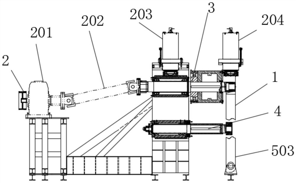
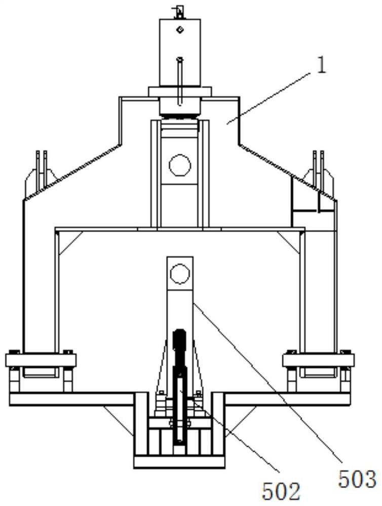
[0025] See Figure 1-5 In the embodiment of the present invention, a gantry heavy-duty expansion unit, including a body 8, a main cylinder 203, a drive shaft assembly, a driven shaft assembly, a power output mechanism 2, and a hydraulic servo mechanism 9, a proactive shaft assembly. The driven shaft assembly is mounted on the body 8 through the limit mechanism 6, and the driven shaft assembly is mounted on the body 8 thro...


PUM


Abstract

The invention discloses a gantry-type heavy-duty expanding forging unit, which comprises a machine body, a main oil cylinder on the machine body, a driving shaft assembly, a driven shaft assembly, a power output mechanism, a gantry frame, a turning support arm, a hydraulic servo mechanism, and a driven shaft assembly. 1. The driving shaft assembly is installed on the body and the movable frame of the main oil cylinder through a limit mechanism; an auxiliary oil cylinder is installed on the gantry frame, and a supporting mechanism is installed on the auxiliary oil cylinder for dismounting or installing the mold; the turning support arm is used for Disassemble or install the workpiece; the hydraulic servo mechanism controls the main oil cylinder and the auxiliary oil cylinder to drive the drive shaft assembly to move synchronously, so as to realize the roll forging of the workpiece by the mold on the drive shaft assembly; Realize the processing of ring parts with a height of more than 500mm, which can completely replace the vertical expansion forging unit or the expensive horizontal expansion forging unit that can meet the processing requirements, and the price is cheaper than that. There are not many external mechanisms for the equipment and the cost is low. .

Description

Technical field [0001] The present invention relates to a metal molding apparatus, and is specifically a gantry heavy-duty expansion and source. Background technique [0002] The continuous advancement of the industrial age has emerged, and the demand for circular parts has grown sharply, and the requirements for their precision and size are increasing. In the past, these annular parts are generally in pressure. Machine or hammer forging, diaphragm forging or die forging, the need for a large size of the annular parts, in the need to ensure the requirements of the metal performance of the processing, and ensure the continuous increase in capacity, the efficiency increases, usually use lying lying The expansion and source of expansion is processed, but in the prior art, for the conventional vertical expansion, the ring can only be machined with a ring of 500mm or less, and the vertical expansion and regeneration for height 500mm can be machined. The equipment itself is expensive. ...

Claims


Application Information

Patent Timeline
Patent Type & Authority Patents(China)
IPC IPC(8): B21K1/76B21J9/14B21J9/18
CPCB21K1/761B21J9/14B21J9/18
Inventor 杜振民杨波姜志超孙建鹏张继伟
Owner 烟台吉森新材料科技有限公司
Learn More