Filling valve for a pressure vessel

a filling valve and pressure vessel technology, applied in the direction of shock absorbers, nuclear elements, nuclear engineering, etc., can solve the problems of high external pressure, premature failure high stress of the pressure vessel, so as to reduce the volume of the fastening part, eliminate the formation of folds, and improve the weld quality

Inactive Publication Date: 2005-09-22
ZF FRIEDRICHSHAFEN AG
View PDF13 Cites 0 Cited by
  • Summary
  • Abstract
  • Description
  • Claims
  • Application Information

AI Technical Summary

Benefits of technology

[0015] It is not important for the weld to be optimal over the entire axial length of the fastening part. The weld must simply be leak-tight toward the outside. For this reason, the minimum of one reinforcing rib proceeds from a bottom part of the pressure-compensating space. In the direction toward the pressure vessel, the fastening part can therefore be fabricated without a reinforcing rib over a certain part of its length, as a result of which the cooling rib effect cannot occur there, and consequently the optimal conditions for a high weld quality are obtained. At the same time, the wall of the fastening part is adequately supported during the welding process.
[0016] In an alternative variant, it is provided according to the invention that the fastening part, in the cross section parallel to the filling channel, is shorter in the direction toward the interior space of the pressure vessel than in the same plane at the outer edge. To avoid an oriented installation position, it is effective here to select a wedge-shaped cross section for the fastening part. This variant almost completely eliminates the formation of folds at the edges of the pressure vessel.
[0017] In addition, the fastening part can become shorter with increasing distance from the outer edge area of the pressure vessel, i.e., the fastening part slants inward from the outer edge of the filling channel. The basic idea is to minimize the volume of the fastening part which is present in the edge area of the pressure vessel.

Problems solved by technology

Such folds could lead to higher stresses and thus to the premature failure of the pressure vessel.
But there is also the problem that the pressure vessel, when used in a vibration damper, is subjected to very high external pressures.
It is disadvantageous in this regard that the filling valves are frequently made of plastic, which cannot withstand such pressures under certain conditions.
The use of an additional coating is not optimal for reasons of production technology, nor is it possible to provide a coating inside a guide part in all types of vibration dampers.
Such ribs, however, negatively affect the length-to-height ratio and thus promote the formation of folds.

Method used


Image

  • Filling valve for a pressure vessel
  • Filling valve for a pressure vessel
  • Filling valve for a pressure vessel

Examples


Embodiment Construction

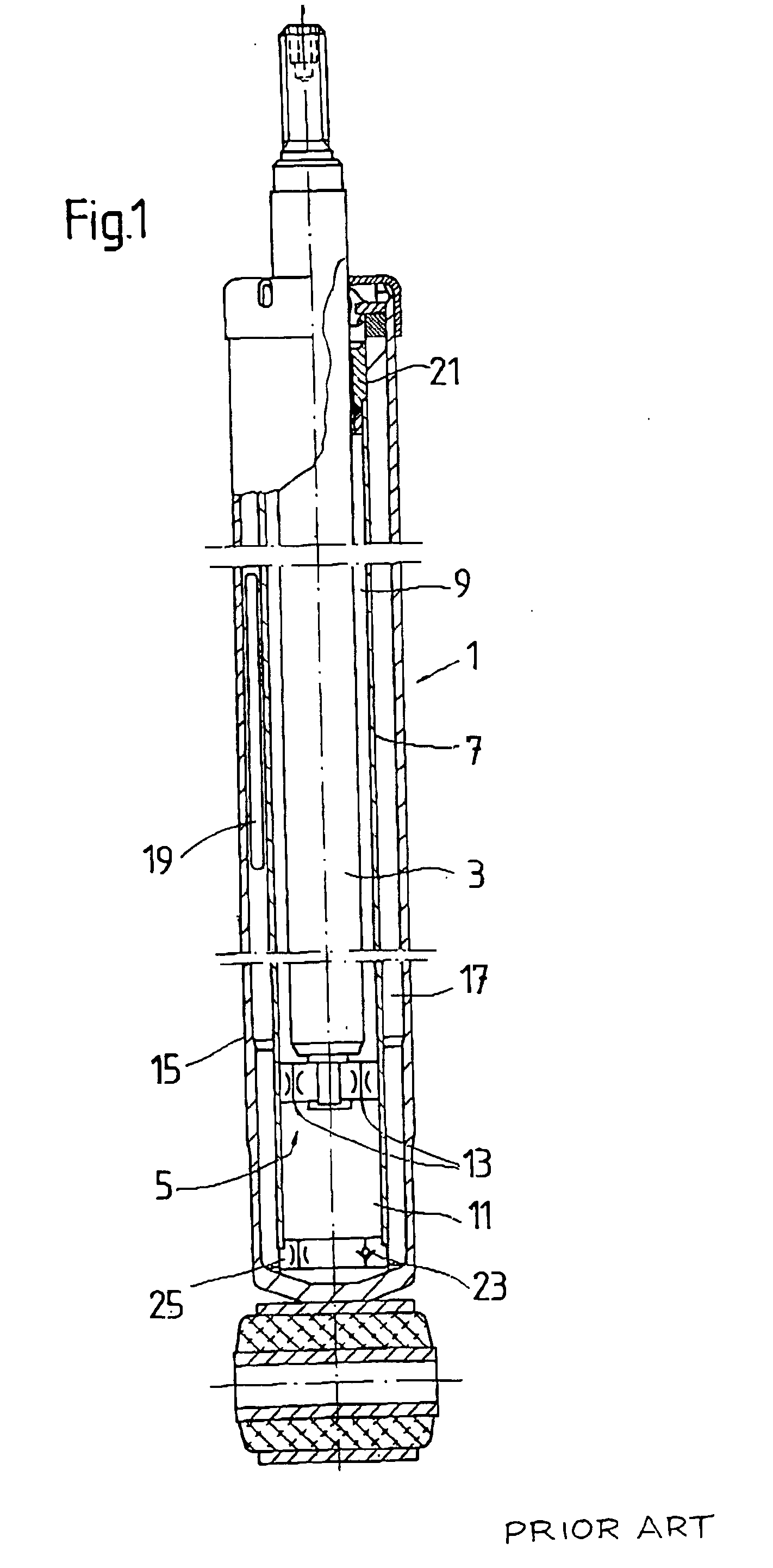
[0025]FIG. 1 shows a vibration damper 1 of the two-tube design known in and of itself, in which a piston rod 3 with a piston 5 is guided with freedom of axial movement inside a pressure tube 7. The piston 5 divides the pressure tube into an upper working space 9 and a lower working space 11, the two working spaces being connected to each other by damping valves 13 in the piston.

[0026] The pressure tube 7 is surrounded by a container tube 15. The inside wall of the container tube and the outside wall of the pressure tube form a compensating space 17, which is completely filled by damping medium and a gas-filled pressure vessel 19, which extends up as far as a piston rod guide 21. At the bottom end of the working space 11, a bottom piece is located, which can be provided with a check valve 23 and a damping valve 25.

[0027] When the piston rod moves, the volume displaced by the piston rod is compensated by a change in the volume of the pressure vessel 19.

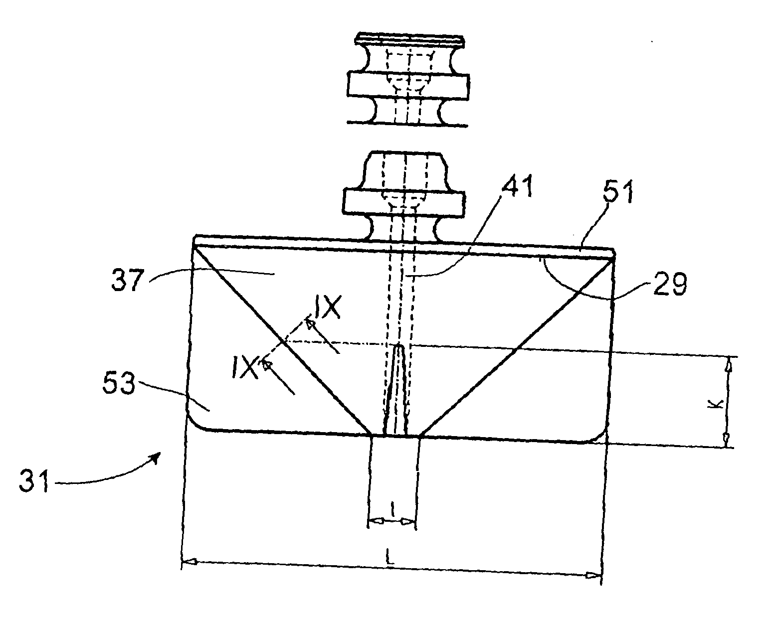
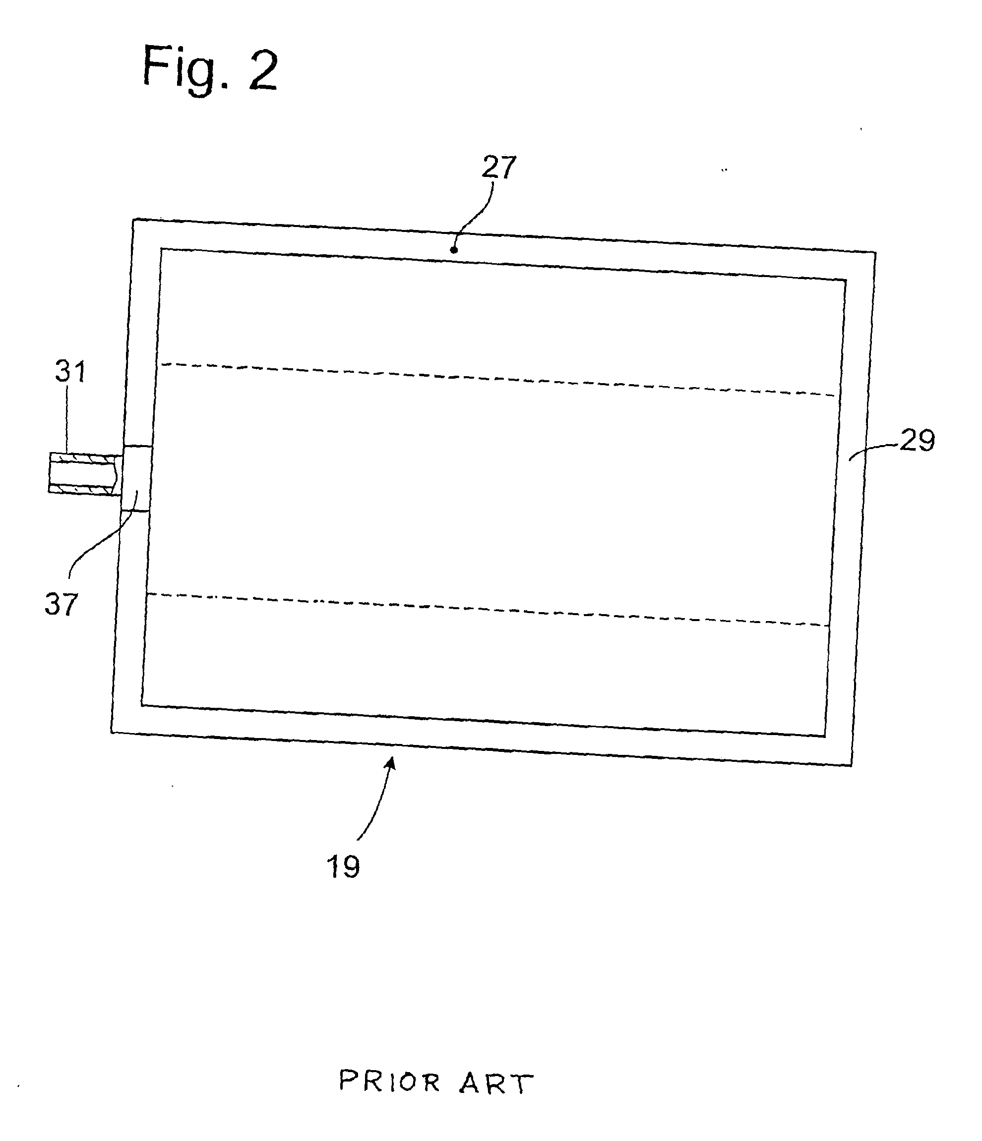
[0028] Referring to FIG. 2, t...


PUM


Abstract

Filling valve for a pressure vessel, which valve is located along with its fastening part along an edge of the pressure vessel, where the fastening part has a radially outward-curved surfaces and encloses a filling channel, and where the fastening part has a pressure-compensating space, the cross section of which is larger than the cross section of the filling channel.

Description

BACKGROUND OF THE INVENTION [0001] 1. Field of the Invention [0002] The invention pertains to a filling valve for fastening to the edge of a pressure vessel, the filling valve having a fastening part having curved outer surfaces and enclosing a filling channel. [0003] 2. Description of the Related Art [0004] U.S. Pat. No. 6,467,760 discloses a filling valve of the general type in question; it is welded into an open edge of the pressure vessel. As can be derived from FIG. 5, the filling valve has a curved surface, which is intended to form a continuous transition with the vessel inside the welded edge, so that no folds are formed inside the enclosing body underneath the filling valve. Such folds could lead to higher stresses and thus to the premature failure of the pressure vessel. [0005] A pressure vessel of the same basic type with a cylindrical filling valve is described in U.S. Pat. No. 6,450,307. In this variant, the filling valve has a conical tip, which is welded into the edge...

Claims


Application Information

Patent Timeline
Patent Type & Authority Applications(United States)
IPC IPC(8): F16F9/092F16F9/43
CPCF16F9/43
Inventor LUTZ, DIETER
Owner ZF FRIEDRICHSHAFEN AG
Why Eureka
Try Eureka