Model supporting and coupling rolling driving device for unsteady force measurement wind tunnel test

A technology of wind tunnel test and drive device, which is applied in the direction of measurement device, aerodynamic test, machine/structural component test, etc. Motor accuracy and other issues, to achieve the effect of increasing the usable length, improving the accuracy, and improving the adaptability

Active Publication Date: 2021-03-19
INST OF HIGH SPEED AERODYNAMICS OF CHINA AERODYNAMICS RES & DEV CENT
View PDF7 Cites 0 Cited by
  • Summary
  • Abstract
  • Description
  • Claims
  • Application Information

AI Technical Summary

Problems solved by technology

[0002] The rolling degree of freedom of the balance strut in the model support device of the traditional high-speed wind tunnel force test is in a locked state, which cannot realize the free rolling motion of the test model. Therefore, the balance cannot measure the unsteady aerodynamic force and moment of the model. The supporting device cannot simulate the dynamic hysteresis effect of aerodynamic force and torque under the condition of aircraft maneuvering
[0003] The free-rolling test device usually used in the dynamic high-speed wind tunnel test releases the degree of freedom of the model's roll, but the free-rolling test cannot be realized because the moving parts such as bearings in the free-rolling test device are affected by their own frictional damping The zero-damping working state of the device affects the simulation authenticity of the free rock movement of the model;
[0004] Moreover, the forced rock test device commonly used in dynamic high-speed wind tunnel tests also has imperfect functions. Because the drive motor is installed in the tail rod, the length of the tail rod available for the model is reduced; at the same time, the model is affected by The roll aerodynamic moment generated by the load will also affect the accuracy of the angle output of the roll drive motor

Method used


Image

  • Model supporting and coupling rolling driving device for unsteady force measurement wind tunnel test
  • Model supporting and coupling rolling driving device for unsteady force measurement wind tunnel test
  • Model supporting and coupling rolling driving device for unsteady force measurement wind tunnel test

Examples


Embodiment 1

[0034] The installation process of this embodiment is as follows:

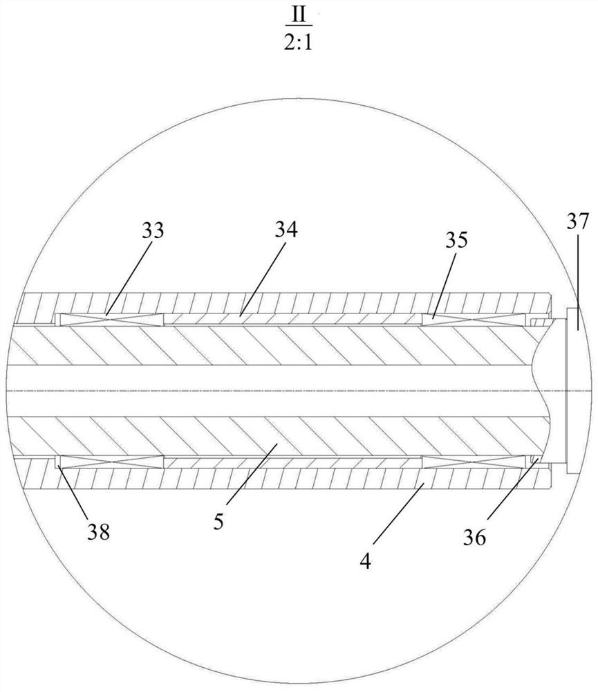
[0035] Insert the front retaining ring 36 from the small-diameter end of the mandrel 5, that is, the rear end, until it contacts the rear end of the balance 37, and install the needle roller bearing I35, bushing I34, and needle roller bearing II33 successively in the same installation method, and the front retaining ring 36. Needle roller bearing I35, shaft sleeve I34, needle roller bearing II33 and mandrel 5 all have clearance fits to ensure flexible rotation of the above parts. The rear end of the mandrel 5 penetrates from the small diameter end of the tail rod 4, that is, the front end, until the needle bearing II33 contacts with the front end 38 of the tail rod 4.

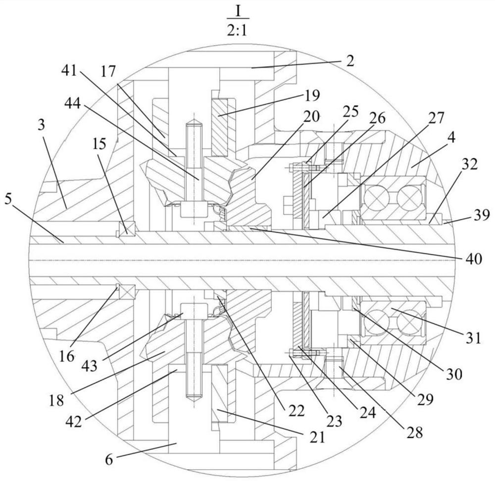
[0036] The inner circle of the thrust bearing 31 is in transition fit with the outer cylinder of the shaft sleeve II 32, the front end surface of the thrust bearing 31 fits the rear end surface of the boss of the shaft sleeve II 32, and the sha...


PUM


Abstract

The invention discloses a model supporting and coupling rolling driving device for an unsteady force measurement wind tunnel test. The device is of a T-shaped rod type structure and comprises a horizontally-arranged tail supporting rod, a mandrel is installed on the central axis of the tail supporting rod, the front end of the mandrel extends out of the tail supporting rod and is fixedly connectedwith a balance, and the balance is fixedly connected with a model. The rear end of the core shaft extends out of the tail supporting rod, a vertical rolling driving servo motor is fixed above the rear end of the core shaft, vertical torque compensation servo motors are symmetrically fixed below the rear end of the core shaft, the rolling driving servo motor drives the core shaft to drive the balance and the model to roll, the torque compensation servo motor outputs same-direction rolling torque, and the energy loss of the rolling driving servo motor is compensated; the back end of the mandrelis coated with the rear section of the support rod, the tail supporting rod is inserted into the supporting rod rear section and is fixedly connected with the supporting rod rear section. The model adaptability of the device is better, and the accuracy of the rolling driving angle is higher.

Description

technical field [0001] The invention belongs to the technical field of high-speed wind tunnel tests, and in particular relates to a model support and coupling rolling drive device for unsteady force measurement wind tunnel tests. Background technique [0002] The rolling degree of freedom of the balance strut in the model support device of the traditional high-speed wind tunnel force test is in a locked state, which cannot realize the free rolling motion of the test model. Therefore, the balance cannot measure the unsteady aerodynamic force and moment of the model. The support device also cannot simulate the dynamic hysteresis effect of aerodynamic force and moment under the condition of maneuvering motion of the aircraft. [0003] The free-rolling test device usually used in the dynamic high-speed wind tunnel test releases the degree of freedom of the model's roll, but the free-rolling test cannot be realized because the moving parts such as bearings in the free-rolling tes...

Claims


Application Information

Patent Timeline
Patent Type & Authority Applications(China)
IPC IPC(8): G01M9/04G01M9/06G01M9/08
CPCG01M9/04G01M9/062G01M9/08
Inventor 李玉平杨海泳赵忠良李浩马上王晓冰陈建中
Owner INST OF HIGH SPEED AERODYNAMICS OF CHINA AERODYNAMICS RES & DEV CENT
Why Eureka
Try Eureka