
Heating device

A heating device and resistance heating technology, which is applied in the fields of electrography, optics, current collectors, etc., can solve the problems of inability to provide voltage for resistance heating elements.

Inactive Publication Date: 2003-08-20
MINOLTA CO LTD
View PDF0 Cites 0 Cited by
  • Summary
  • Abstract
  • Description
  • Claims
  • Application Information

AI Technical Summary

Problems solved by technology

In the early stage before the carbon film is formed on the contact surface of the power receiving member in contact with the power feeding member due to the sliding between the power feeding member and the power receiving member, the contact on the mutual contact surface of the power feeding member and the power receiving member The resistance changes significantly, so that the voltage cannot be stably supplied to the resistance heating element

Method used


Image

  • Heating device
  • Heating device
  • Heating device

Examples


Embodiment Construction

[0054] Embodiments of the present invention will be described in detail below in conjunction with the accompanying drawings.

[0055] (first embodiment)

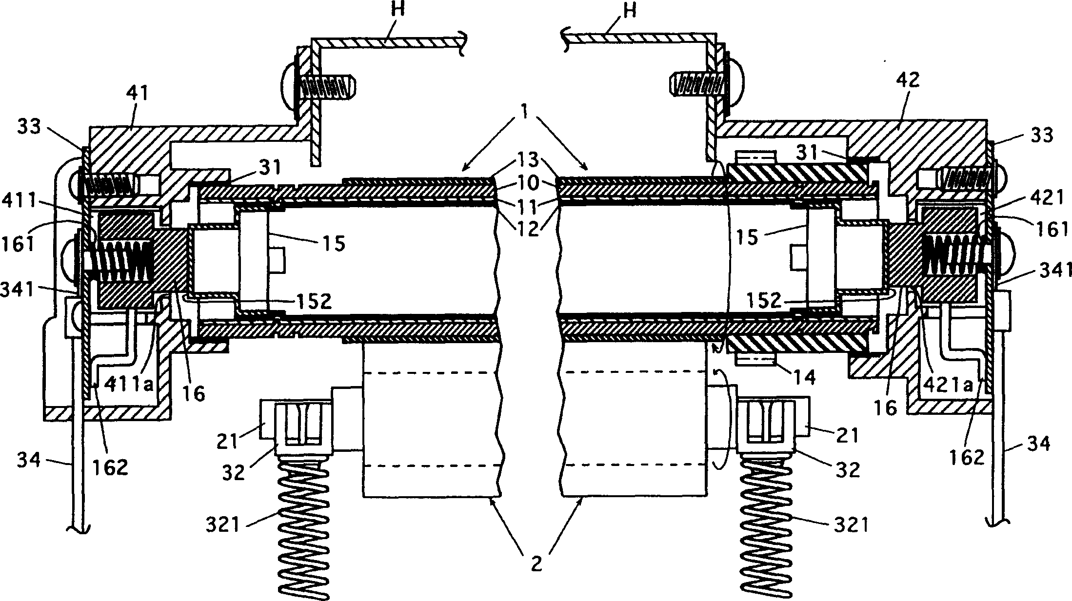
[0056] figure 1 It is a sectional view of a heating roller device (heating device) of the present invention. especially, figure 1 is a sectional view of a fixing device equipped with a heat roller unit. This fixing device is installed in an electrophotographic imaging device such as a copying machine, a printer or a facsimile machine, and can be used to fix an unfixed toner image on a record or an unfixed toner image by applying heat and pressure thereto. On the paper of shadows.

[0057] This fixing device has a heating roller device including a heating roller 1 and a pressure roller 2 opposite to the heating roller 1 .

[0058] The heating roller 1 is rotatably mounted at opposite ends thereof by bearings 31 . The bearing 31 on the left side of the drawing is supported by a bracket 41 mounted on the housing H of the ...


PUM

PropertyMeasurementUnit
surface roughnessaaaaaaaaaa

Abstract

A heating device comprises an endless rotary member, a resistance heating member, a current receiver member provided at the endless rotary member and a current supply member being in contact with the current receiver member. In a form, the current supply member is made of a sintered material containing copper and carbon, and a content of the copper in the sintered material is in a range from 55% to 80% by weight. In another form, a contact surface of the current receiver member is formed of a material harder than the current supply member. The contact surface of the current receiver member and the contact surface of the current supply member have surface roughnesses satisfying a relationship of (surface roughness of the current receiver member)<=(surface roughness of the current supply member). The surface roughness Ra of the current receiver member is in a range from 0.3 mu m to 5.5 mu m. The surface roughness Ra of the current supply member is equal to or smaller than 5.5 mu m.

Description

technical field [0001] The present invention relates to a heating device which can be used for heating an unfixed image in a fixing device installed in an electrophotographic image forming device such as a copying machine, a printer, etc. An unfixed image such as an image is fixed to a recording member carrying the unfixed image. Background technique [0002] A fixing device in an image forming device such as a printer or a copying machine generally includes a heating device provided with a heating roller. A recording member carrying an unfixed image such as a toner image is moved between a heated roller and a supporting member (usually a pinch roller) opposed thereto to heat and press the unfixed image to fix it. Fixes to the record. [0003] In many instances, the heated roll includes a heater such as a halogen lamp heater, and the roll is heated by heat radiated from the heater. [0004] However, in a heating device including a heating roller including a heater such as...

Claims


Application Information

Patent Timeline
Patent Type & Authority Patents(China)
IPC IPC(8): G03G15/20H01R39/20
CPCG03G15/2053H01R39/20
Inventor 森上祐介坂田俊雄岡林英二小鹭祥史
Owner MINOLTA CO LTD
Learn More