A kind of assembly device for wooden sword production

A technology for assembling devices and wooden swords, which is applied in the direction of adhesive application devices, wood processing equipment, manufacturing tools, etc., can solve the problems of low assembly efficiency and achieve the effect of reducing manual operations and improving efficiency

Active Publication Date: 2022-07-05
陈正林
View PDF9 Cites 0 Cited by
  • Summary
  • Abstract
  • Description
  • Claims
  • Application Information

AI Technical Summary

Problems solved by technology

[0004] In order to overcome the shortcomings of the manual assembling method that glue needs to be applied multiple times, and the sword body and hilt are repeatedly taken, and the assembly efficiency is low, the technical problem is to provide a glue that can be automatically applied without repeatedly taking the sword body and hilt, and improve the quality of the sword. Assembly device for wooden sword production with high assembly efficiency

Method used


Image

  • A kind of assembly device for wooden sword production
  • A kind of assembly device for wooden sword production
  • A kind of assembly device for wooden sword production

Examples


Embodiment 1

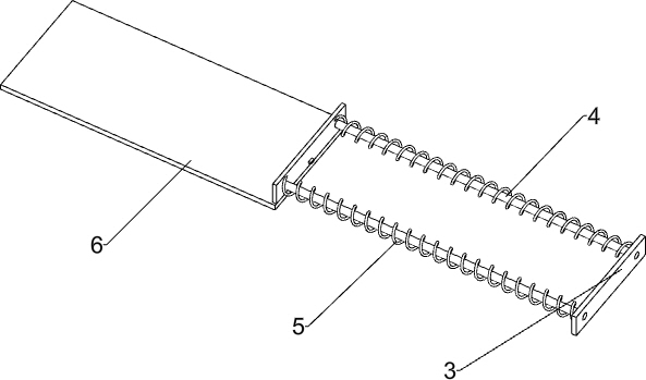
[0041] An assembly device for the production of wooden swords, such as Figure 1-2 As shown, it includes a base 1, a mounting plate 2, a square frame 3, a guide rod 4, a first elastic member 5, a placing plate 6, a transfer table 7, a sliding plate 8, a discharging mechanism 9 and a pressing mechanism 10. A mounting plate 2 is provided, a square frame 3 is embedded on the right side of the mounting plate 2, and guide rods 4 are provided on the front and rear sides of the right wall of the square frame 3. The left part of the guide rod 4 is slidably connected with a placing plate 6. A first elastic member 5 is arranged between the right wall and the right wall of the square frame 3. The first elastic member 5 is wound around the guide rod 4. A transfer table 7 is installed on the left side of the top of the mounting plate 2, and a transfer table 7 is installed on the right side. The sliding plate 8, the sliding plate 8 is inclined to the right, a discharging mechanism 9 is prov...

Embodiment 2

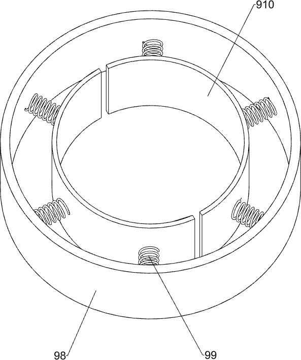
[0044] Specifically, as Figure 3-5 As shown, the discharging mechanism 9 includes a cylinder 91, a first rotating shaft 92, a circular plate 93, a guide column 95, a circular disc 96, a second elastic member 97, a ring frame 98, a third elastic member 99 and a semicircular clamping block 910, The right rear part of the mounting plate 2 is provided with a cylinder 91, a first rotating shaft 92 is rotatably installed inside the cylinder 91, a circular plate 93 is provided in the middle and the upper part of the first rotating shaft 92, and the upper circular plate 93 is evenly provided with six There are circular grooves 94, and guide posts 95 are evenly connected in a circular shape between the circular plates 93 on the upper and lower sides. The tops of the guide posts 95 are equipped with discs 96. The discs 96 are slidably located in the circular grooves 94. A second elastic member 97 is evenly arranged between the bottom of 96 and the lower circular plate 93, the second el...

Embodiment 3

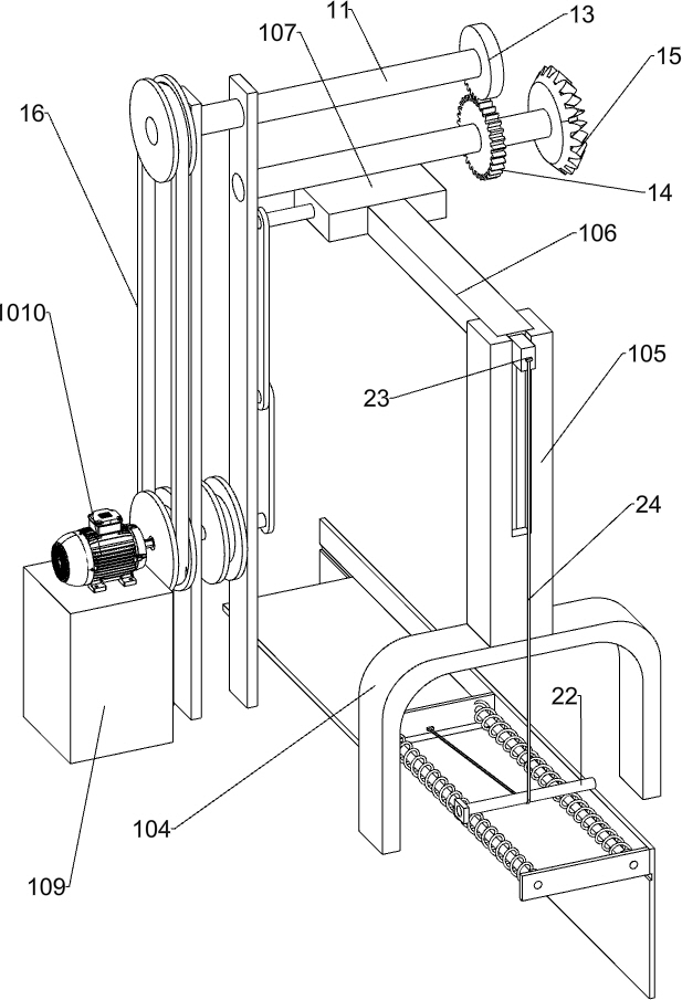
[0049] refer to Figure 6-7 As shown, it also includes a first rotating shaft 11, a second rotating shaft 12, a missing gear 13, a circular gear 14, a bevel gear 15, a first belt drive assembly 16 and a second belt drive assembly 17. The upper part of the fixed plate 101 is rotatably provided with The first rotating shaft 11 has a second rotating shaft 12 rotatably mounted on the upper part of the fixing plate 101 on the rear side. The second rotating shaft 12 is located below the first rotating shaft 11 . A circular gear 14 is provided, the circular gear 14 meshes with the missing gear 13, the number of teeth of the missing gear 13 is one-sixth of the number of teeth of the circular gear 14, the rear end of the second rotating shaft 12 and the upper end of the first rotating shaft 92 are provided with bevel gears 15 , the two bevel gears 15 are meshed, the first belt drive assembly 16 is connected between the front side of the first rotating shaft 11 and the front side of the...


PUM


Abstract

The invention relates to an assembly device, in particular to an assembly device for wooden sword production. Technical problem: To provide an assembly device for wooden sword production that can automatically apply glue without repeatedly taking the sword body and the hilt to improve assembly efficiency. The technical scheme of the present invention is an assembling device for wooden sword production, comprising: a base, a mounting plate is arranged on the top of the base, a square frame is embedded in the side of the mounting plate, and guides are installed on both sides of the front side of the right wall of the square frame A rod; a placing plate, the end of the guide rod is slidably installed with a placing plate, a first elastic piece is connected between the placing board and the square frame, and the first elastic piece is wound around the guide rod. The invention can fix the blade body through the feeding mechanism, and prevent the position of the blade body from shifting during the assembly process. At the same time, the design of multiple semi-circular clamping blocks can fix multiple blade bodies without repeatedly taking the blade body. , Through the pressing mechanism, the sword body is driven to move down, so that the sword body is automatically inserted into the hilt, and the efficiency of wooden sword assembly is improved.

Description

technical field [0001] The invention relates to an assembly device, in particular to an assembly device for wooden sword production. Background technique [0002] At present, in the process of producing wooden swords, in order to facilitate the production of the sword body and the hilt, the sword body and the sword hilt are usually produced separately. The handle is assembled together. When the number of wooden swords to be assembled is too many, the worker needs to apply glue to the sword body several times and insert the sword body into the hilt. After assembling a wooden sword, the worker needs to take off the next one to be assembled. The body and hilt of the sword, the assembly efficiency of the entire wooden sword is low. [0003] In view of the shortcomings of the above-mentioned manual assembling of wooden swords, it is necessary to manually apply glue many times and take the sword body and the hilt repeatedly. It is necessary to design a kind of wooden sword that c...

Claims


Application Information

Patent Timeline
Patent Type & Authority Patents(China)
IPC IPC(8): B27M3/00B27G11/00B27G11/02
CPCB27M3/0086B27G11/00B27G11/02
Inventor 陈正林
Owner 陈正林
Why Eureka
Try Eureka