Iron piece automatic heat treatment device

A technology for heat treatment devices and iron parts, applied in heat treatment equipment, quenching devices, manufacturing tools, etc., can solve the problems of low heat treatment efficiency of iron parts, easy burns of workers, etc., and achieve the effect of preventing excessive left and right movement and preventing position deviation

Active Publication Date: 2020-11-03
郴州弘德尚铸造有限公司
View PDF9 Cites 3 Cited by
  • Summary
  • Abstract
  • Description
  • Claims
  • Application Information

AI Technical Summary

Problems solved by technology

[0004] In order to overcome the shortcomings of manually picking up iron pieces in the manual heat treatment method, workers are easy to burn, and the heat treatment efficiency of iron pieces is low. Automatic heat treatment device for iron parts in water to improve operational safety

Method used


Image

  • Iron piece automatic heat treatment device
  • Iron piece automatic heat treatment device
  • Iron piece automatic heat treatment device

Examples


Embodiment 1

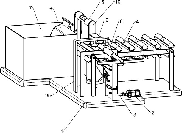
[0044] An automatic heat treatment device for iron parts, such as figure 1 As shown, it includes a base 1, a motor 2, an output shaft 3, an intermittent feeding mechanism 4, an intermittent lifting mechanism 5, a blanking plate 6, and a cooling box 7. A motor 2 is installed on the right front of the base 1, and the output shaft of the motor 2 is connected to There is an output shaft 3, the right side of the base 1 is provided with an intermittent feeding mechanism 4, the intermittent feeding mechanism 4 is connected to the output shaft 3, a cooling box 7 is installed on the left side of the base 1, and the rear side of the right wall of the cooling box 7 is connected to the front part of the right side of the base 1 An intermittent lifting mechanism 5 is arranged between them, and the intermittent lifting mechanism 5 is connected with the intermittent feeding mechanism 4, and a blanking plate 6 is installed on the upper part of the cooling box 7 rear wall.

[0045]When the iro...

Embodiment 2

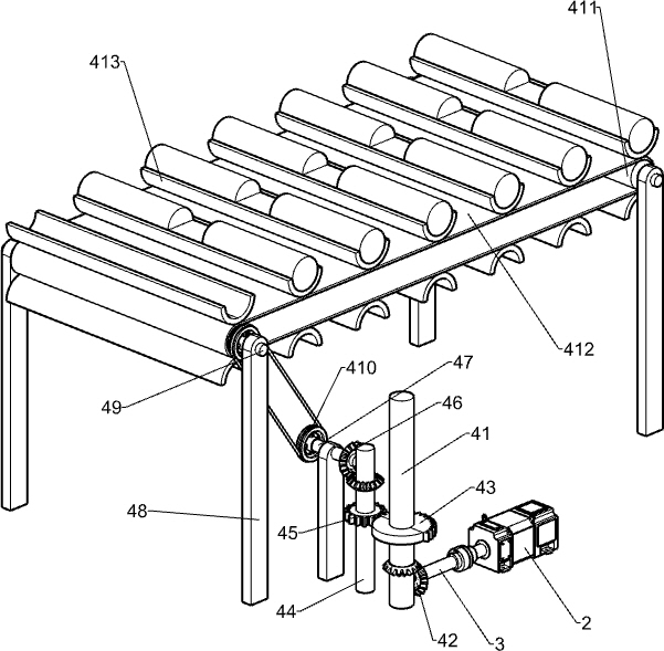
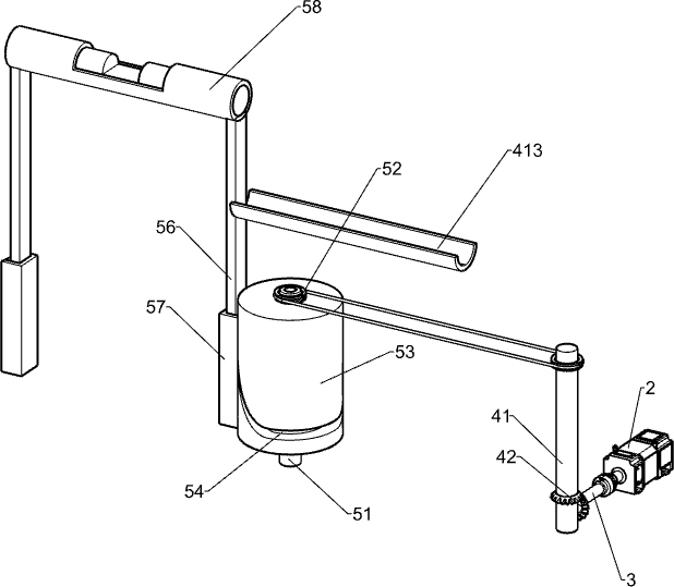
[0047] according to Figure 1-4 As shown, the intermittent feeding mechanism 4 includes a first rotating shaft 41, a first bevel gear 42, a half-tooth bull gear 43, a transmission shaft 44, a first full-tooth pinion 45, a second bevel gear 46, a second rotating shaft 47, a support Rod 48, third rotating shaft 49, first belt assembly 410, transmission roller 411, conveyor belt 412 and iron piece placement plate 413, the right front side of the base 1 is provided with a first rotating shaft 41, and the first rotating shaft 41 is located at the front side of the output rotating shaft 3 The first bevel gear 42 is installed on the lower part of the first rotating shaft 41 and the front side of the output rotating shaft 3, and the first bevel gears 42 on both sides mesh with each other. Located above the first bevel gear 42, a transmission shaft 44 is rotatably installed on the base 1 on the left side of the first rotating shaft 41. The middle part of the transmission shaft 44 is pr...

Embodiment 3

[0052] Specifically, such as figure 1 and Figure 5-6 As shown, it also includes an intermittent push-out mechanism 8, and the intermittent push-out mechanism 8 includes a fourth rotating shaft 81, a second full-toothed pinion 82, a rotating rod 83, a pushing slide rail 84, a push rod 85 and a support frame 86, and the first rotating shaft 41 On the base 1 on the right side, a fourth rotating shaft 81 is rotatably installed, and a second full-tooth pinion 82 is installed on the bottom of the fourth rotating shaft 81. The second full-tooth pinion 82 can mesh with the half-tooth bull gear 43, and the fourth rotating shaft 81 The upper end is connected with a rotating rod 83, the right end of the rotating rod 83 is slidably connected with a push slide rail 84, the middle part of the push slide rail 84 is equipped with a push rod 85, and the base 1 on the right front side of the conveyor belt 412 is provided with a support frame 86, and the left side of the push rod 85 Located at...


PUM


Abstract

The invention relates to a heat treatment device, in particular to an iron piece automatic heat treatment device. According to the iron piece automatic heat treatment device, an iron piece can be automatically replaced, the heated iron piece is automatically thrown into water, and the operation safety is improved. According to the technical scheme, the iron piece automatic heat treatment device comprises a base and a cooling box; a motor is installed on the side of the base, an output rotating shaft is installed on an output shaft of the motor, and an intermittent feeding mechanism is arrangedon the side, close to the motor, of the base; and the cooling box is arranged on the side, away from the motor, of the base, and an intermittent lifting mechanism is arranged between the side of thecooling box and the side of the base. According to the iron piece automatic heat treatment device, by means of the intermittent lifting mechanism, the to-be-heated iron piece automatically moves upwards to make contact with a quenching device to be subjected to iron piece heat treatment, automatic feeding is achieved through an intermittent push-out mechanism, the heated iron piece automatically slides into the cooling box, and the iron piece does not need to be pushed manually.

Description

technical field [0001] The invention relates to a heat treatment device, in particular to an automatic heat treatment device for iron pieces. Background technique [0002] In order to improve the strength of the iron parts, enhance the wear resistance and oxidation resistance, after the iron parts are produced, they will be heat treated manually, that is, the iron parts will be placed under the quenching device to be heated manually. After heating, the iron parts will be manually heated The iron parts are quickly dropped into the water to cool down, and the strength and oxidation resistance of the iron parts after cooling are improved. However, this method of heat treatment of iron parts requires workers to take the iron parts repeatedly and throw the heated iron parts repeatedly. Influent, the heat treatment efficiency of iron parts is low, and if the manual operation is improper, it is easy to be scalded by the quenching device. [0003] In order to solve the shortcomings...

Claims


Application Information

Patent Timeline
Patent Type & Authority Applications(China)
IPC IPC(8): C21D1/63C21D6/00
CPCC21D1/63C21D6/00
Inventor 张小刚
Owner 郴州弘德尚铸造有限公司
Why Eureka
Try Eureka