Automobile inner and outer mirror shell production mold

A technology for molds and automobiles, which is applied to household appliances, other household appliances, household components, etc., can solve problems such as affecting work efficiency and inability to cool the mirror casing, and achieve the effect of improving work efficiency, automation and labor saving, and beautiful mirror casings.

Inactive Publication Date: 2022-03-25
YINGTAN KSD ELECTRONICS PLASTIC
View PDF1 Cites 3 Cited by
  • Summary
  • Abstract
  • Description
  • Claims
  • Application Information

AI Technical Summary

Problems solved by technology

[0005] In order to overcome the disadvantage that the existing production mold cannot cool the mirror shell after the mirror shell is formed, other cooling equipment is needed, which affects the work efficiency. The technical problem of the present invention is to provide a high work efficiency and can Production mold for automotive interior and exterior mirror housings that automatically cools molded mirror housings

Method used


Image

  • Automobile inner and outer mirror shell production mold
  • Automobile inner and outer mirror shell production mold
  • Automobile inner and outer mirror shell production mold

Examples


Embodiment 1

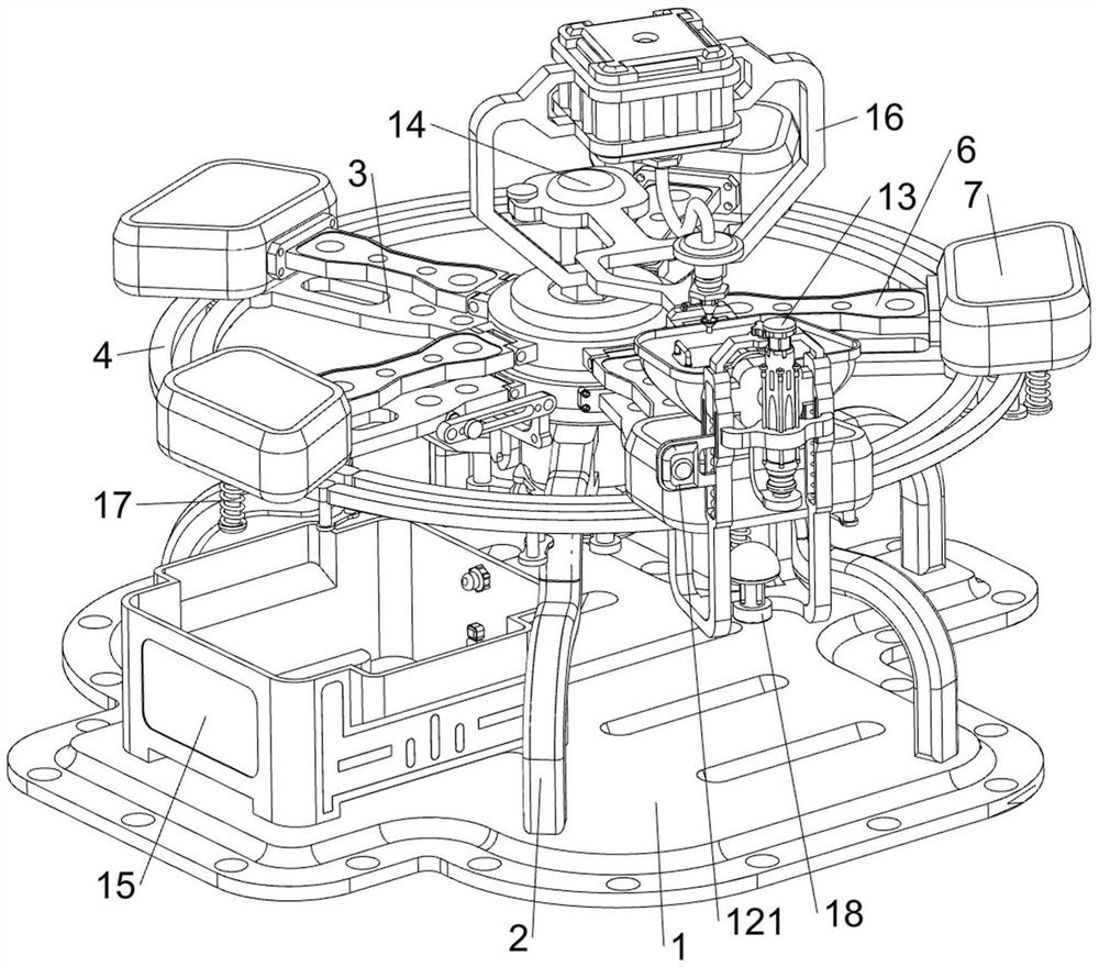
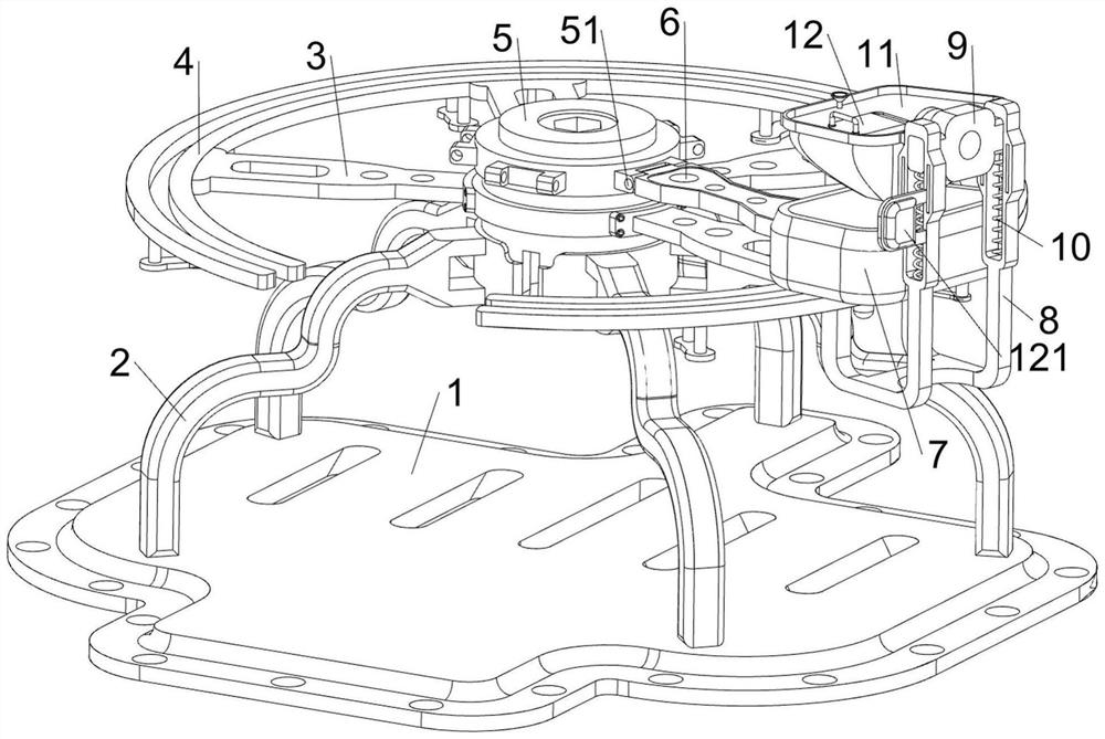
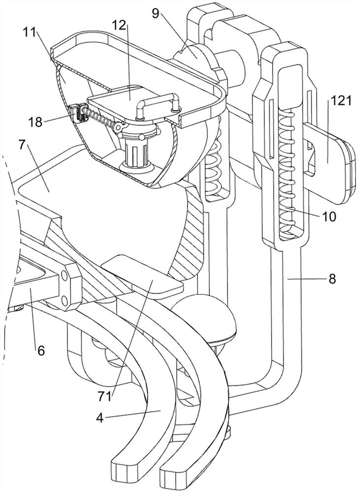
[0039] A production mold for the interior and exterior mirror shells of automobiles, in Figure 1-3 As shown in , it includes a bottom plate 1, a first support frame 2, a first connecting rod 3, an annular block 4, a rotating shaft 5, a first connecting shaft 51, a second connecting rod 6, a molding die 7, a push plate 71, a limiter Position frame 8, first slider 9, return spring 10, compacting module 11, baffle plate 12, control panel 121, lifting mechanism 13, rotating mechanism 14 and cooling mechanism 15, the top of bottom plate 1 is provided with first support frame 2, The upper side of the first support frame 2 is annularly connected with four first connecting rods 3 along the circumferential direction, and an annular block 4 for guiding is connected between the outer sides of the four first connecting rods 3 , and the top of the first support frame 2 is rotated in the middle. Rotating shaft 5 is arranged, and the outer side of rotating shaft 5 is connected with five fir...

Embodiment 2

[0045] On the basis of Example 1, in figure 1 and Figure 10As shown in the figure, it also includes an injection molding mechanism 16, and the injection molding mechanism 16 includes a third support frame 160, a charging box 161, an electric heating pipe 162, a support block 163, a nozzle 164, a booster pump 165, a delivery pipe 166 and a first pressure Sensor 167, the middle part of the third connection block 144 is connected with a third support frame 160 by bolt connection, the third support frame 160 is provided with a charging box 161 for storing the melt, and the four sides of the outer wall of the charging box 161 are provided with There are three electric heating tubes 162 for heating the melt, a support block 163 is provided on the right side of the top of the third connecting block 144, and a nozzle 164 for spraying the melt is arranged on the support block 163, and the nozzle 164 is in contact with the feeding pipe And aligned, the right side of the bottom of the ...


PUM


Abstract

The invention relates to a die, in particular to a die for producing inner and outer mirror shells of an automobile. According to the technical aims, the production mold for the inner and outer mirror shells of the automobile is high in working efficiency and capable of automatically cooling a formed mirror shell. According to the technical scheme, the automobile inner and outer mirror shell production mold comprises a bottom plate, a first supporting frame, first connecting rods, an annular block, a rotating shaft and the like, the first supporting frame is arranged at the top of the bottom plate, the four first connecting rods are annularly connected to the upper side of the first supporting frame in the circumferential direction, and the annular block is connected between the outer sides of the four first connecting rods; a rotating shaft is rotationally arranged in the middle of the top of the first supporting frame. An operator presses the control switch, the electric push rod works to drive the compaction module to move downwards to make contact with the shaping mold, the operator can inject molten liquid into a gap between the compaction module and the shaping mold for forming, the compaction module does not need to be manually pushed through the operation, and the operation is more stable and accurate.

Description

technical field [0001] The invention relates to a mold, in particular to a production mold for an automobile inner and outer mirror shell. Background technique [0002] With the development of the economy, people usually use cars for more convenient travel, which greatly improves the efficiency and convenience of travel. The rearview mirror in the auto parts is the driver sitting in the cab seat to directly obtain the rear and side of the car. and tools for external information such as below, the outer shell of the rearview mirror is made of plastic material, which is processed by injection mold. [0003] Publication No. CN212498756U is a continuous injection mold for the production of automobile rearview mirror shells, which aims to solve the problems that the production of automobile rearview mirror shells needs one-time molding, and the traditional injection molds have poor production continuity, low degree of automation, and low processing efficiency. It includes a stri...

Claims


Application Information

Patent Timeline
Patent Type & Authority Applications(China)
IPC IPC(8): B29C45/26B29C45/06B29C45/73B29C45/76B29L31/30
CPCB29C45/26B29C45/06B29C45/73B29C45/76B29C2945/76006B29C2945/76304B29C2945/76351B29L2031/30
Inventor 潘斌潘来宾
Owner YINGTAN KSD ELECTRONICS PLASTIC
Why Eureka
Try Eureka