Eureka AIR delivers breakthrough ideas for toughest innovation challenges, trusted by R&D personnel around the world.

Soil outlet beam plate structure by reversed construction method and construction method

A technology of beam-slab structure and construction method, which is applied in the direction of basic structure engineering, underwater structures, excavation, etc., can solve the problems of increasing the probability of water leakage, reducing the size of the excavation hole, and being easy to be damaged, so as to improve construction efficiency and increase Net size, the effect of avoiding damage

Inactive Publication Date: 2020-11-03
SHANGHAI NO 4 CONSTR
View PDF3 Cites 1 Cited by
  • Summary
  • Abstract
  • Description
  • Claims
  • Application Information

AI Technical Summary

Problems solved by technology

[0003] One is the reduction in the size of the excavation opening: the overhanging beams and slabs plus the reserved steel bars invade the large size of the excavation opening, so the actual effective size of the excavation opening has shrunk seriously;
[0004] The second is that the steel bars reserved for the excavation port are stretched out, which are easily damaged during the excavation of the earth, which will increase the cost of planting bars in the later stage;
[0005] The third is that due to the long time reserved for steel bars at the excavation port, improper protection of the straight thread teeth will cause corrosion and failure, which will affect the construction quality of the post-build structure;
[0006] Fourth, for the roof area of ​​the excavation port, the water-stop steel plate is easily damaged during excavation, which increases the probability of water leakage

Method used


Image

  • Soil outlet beam plate structure by reversed construction method and construction method
  • Soil outlet beam plate structure by reversed construction method and construction method
  • Soil outlet beam plate structure by reversed construction method and construction method

Examples


Embodiment 1

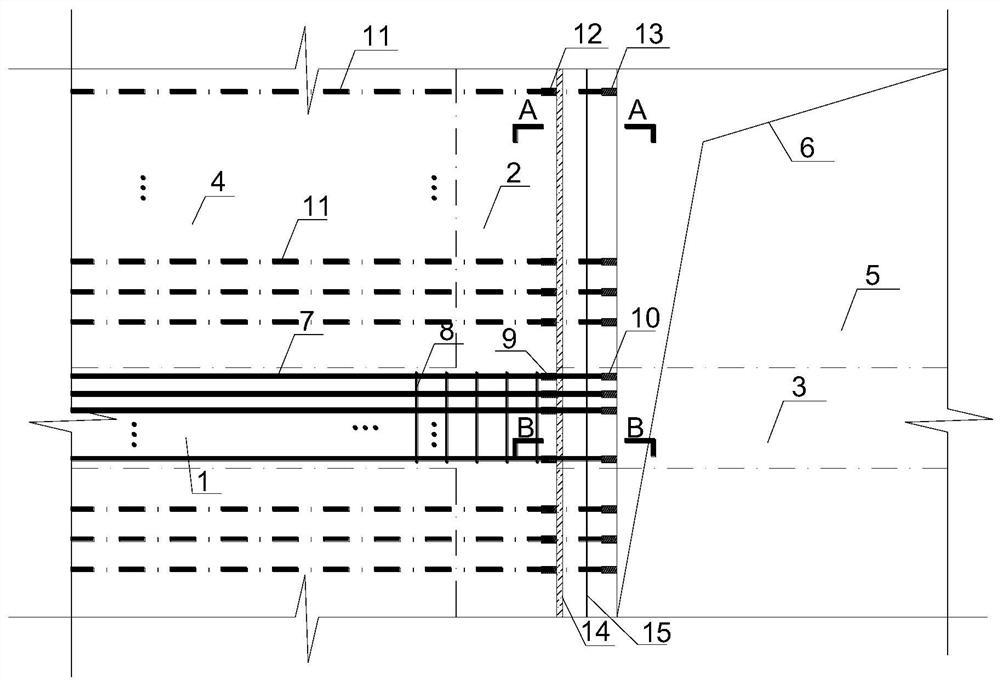
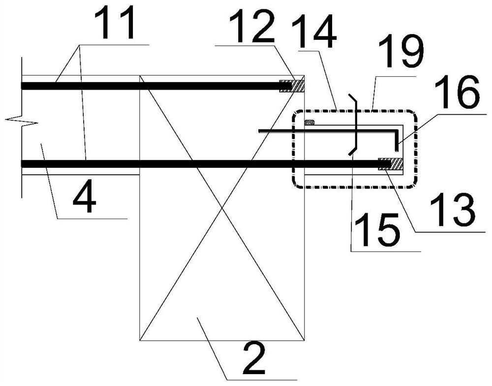
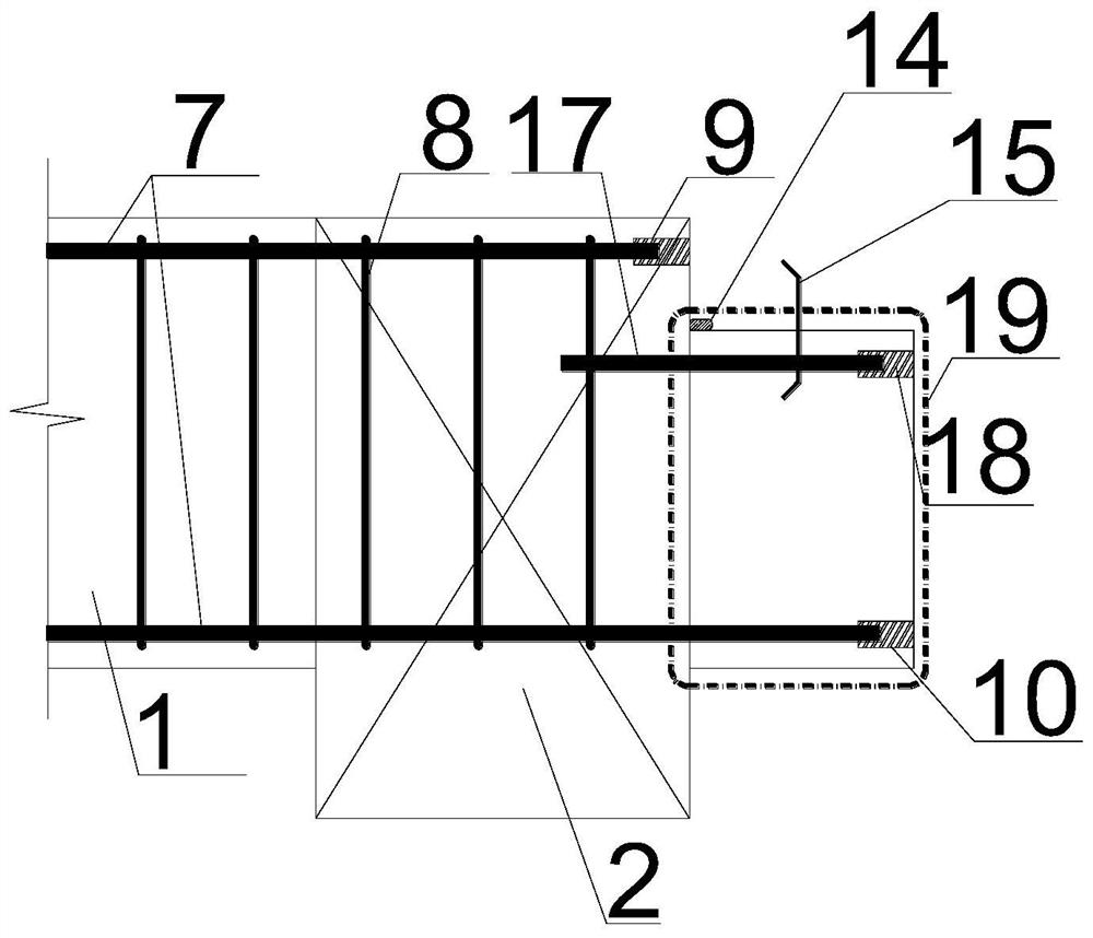
[0036] Combine below Figure 1 to Figure 5 , detailing the structural composition of the beam-slab structure of the excavation port by the reverse method of the present invention.

[0037] Please refer to Figure 1 to Figure 5, a beam-slab structure of the excavation mouth by the reverse method, including several pre-built components and post-construction components forming an integrated structure, the first-built components include the excavation mouth side beam 2, the first structural beam 1 passing through the excavation opening, and the first floor slab 4 The building components include structural beams 3 in the excavation opening and floor plates 5 in the excavation opening. The side beam 2 of the excavation opening is provided with a cantilevered member 19 near the unearthed opening, and a Z-shaped structure is formed between the side beam 2 of the excavation opening and the cantilevered member 19; The top of the cantilever member 19 is lowered by half the thickness of ...


PUM


Abstract

The invention provides a soil outlet beam plate structure by a reversed construction method and a construction method, belongs to the technical field of building construction, and aims to solve the problems that when the existing reversed construction method is used for constructing a soil outlet, the space is small due to existence of connecting steel bars and the connecting steel bars are easy to damage. The structure comprises a plurality of pre-built components and post-built components, a cantilever component is arranged on the sides close to the soil outlet, of soil outlet edge beams ofthe pre-built components, and the cantilever component and the pre-built components form a Z-shaped structure; the top of the cantilever component is lowered by half of the thickness a the floor platein the soil outlet, and a bottom beam plate area of the cantilever component is consistent with the post-built beam plate area; a soil outlet inner structural beam of the post-built components is fixedly connected with the soil outlet edge beams and a soil outlet penetrating pre-built structural beam through the cantilever component; and the floor plate in the soil outlet is used for filling a reserved hole in the soil outlet area. According to the construction method, a beam plate close to the soil outlet is designed to be of the Z-shaped structure, a steel bar connector is pre-buried in thepre-built components and used for being connected with the steel bars of the post-built components, and finally, hole reserving and vacancy filling construction of the soil outlet area is performed.

Description

technical field [0001] The invention relates to the technical field of building construction, in particular to a beam-slab structure and a construction method of an excavation port by the reverse method. Background technique [0002] At present, in the reverse construction of the foundation pit, the hole left at the excavation entrance is generally solved by reserving steel bars. The traditional method is: first, the boundary beam of the excavation opening is extended 500mm inward to the excavation opening as the construction joint of the excavation opening; Extend 300mm from the position of the construction joint; when the excavation opening is blocked in the final stage, after the template support is completed, remove the residue and garbage at the excavation opening, straighten and bind the steel bars, and pour concrete. This traditional approach has the following disadvantages: [0003] One is the reduction in the size of the excavation opening: the overhanging beams an...

Claims


Application Information

Patent Timeline
IPC IPC(8): E02D17/02E02D29/045E02D31/02
CPCE02D17/02E02D29/045E02D31/02
Inventor 朱利君汪小林段博王伟孔德志汪宇峰邢文杰
Owner SHANGHAI NO 4 CONSTR
Why Eureka
Eureka Blog
Learn More