Non-restraint connecting joint of support type damper and existing RC frame structure

A technology for frame structure and connecting nodes, which is applied in the direction of building components, building types, building structures, etc., can solve the problems of affecting the seismic performance of the structure, complicated construction operations, shear yielding of beam ends, etc. The effect of flexural/shear bearing capacity differential, reducing the effect of support energy dissipation efficiency

Active Publication Date: 2020-11-03
QINGDAO TECHNOLOGICAL UNIVERSITY +1
View PDF7 Cites 1 Cited by
  • Summary
  • Abstract
  • Description
  • Claims
  • Application Information

AI Technical Summary

Problems solved by technology

[0007] The technical problem to be solved by the present invention is the research on the existing problems in the existing RC frame structure when the support type damper is used in the prior art. There are also the following problems: (1) the node area cannot be functionally divided, As the connection area between the gusset plate and the beam and the expected plastic hinge area of ​​the beam, the two will affect the seismic performance of the structure due to the interaction; (2) the gusset plate is only connected to the beam, so that the

Method used


Image

  • Non-restraint connecting joint of support type damper and existing RC frame structure
  • Non-restraint connecting joint of support type damper and existing RC frame structure
  • Non-restraint connecting joint of support type damper and existing RC frame structure

Examples


Example Embodiment

[0035] Example 1:

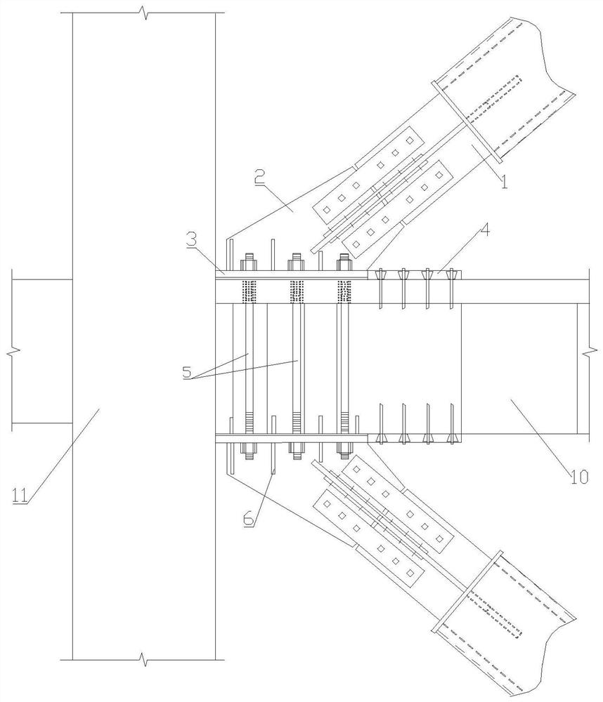
[0036] like figure 1 As shown, a kind of unconstrained connection node between a braced damper and an existing RC frame structure, including a braced damper 1, an unconstrained gusset plate 2, an end plate 3, a shear plate 4, and a tie rod 5;

[0037] Among them, one end of the unconstrained gusset plate 2 is connected to the beam 10 through the end plate 3, and the other end is connected to the support type damper 1;

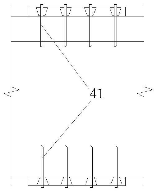
[0038] At the beam end node, in addition to being subjected to the bending moment, it is also subjected to a large axial force from the support, which is the key part of the force. The functions are partitioned to avoid the effect of short beams and short columns formed by the plastic hinge area at the beam end section. like Figure 5 As shown, the beam 10 is sequentially divided into a tensile functional area 101, a shear functional area 102, and an expected plastic hinge area 103 at the beam end from the end near the column to the end f...

Example Embodiment

[0043] Example 2:

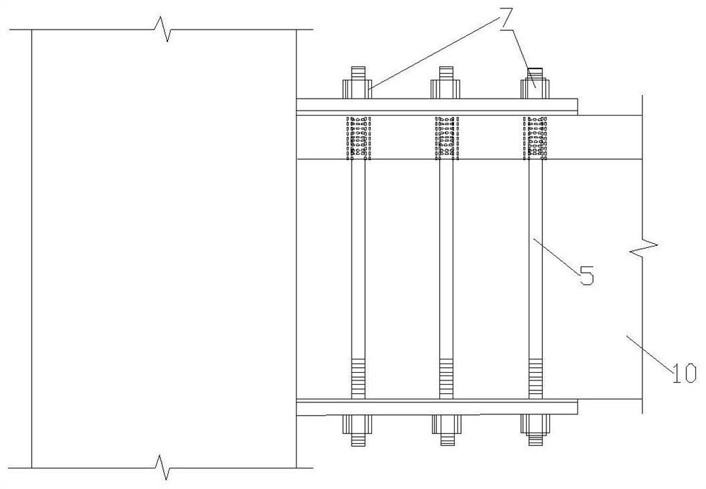
[0044] like Figure 7 As shown, when the span of the beam is small, the support damper can be arranged in the form of monoclinic support.

[0045] All the other are identical with embodiment 1.

Example Embodiment

[0046] Example 3:

[0047] like Figure 8 As shown, when the span of the beam is large, the support damper can be arranged in the form of herringbone + V-shaped support; furthermore, when it is arranged in the middle of the beam span, it is not necessary to adjust the load-carrying capacity level difference, and it is not necessary to carry out FRP reinforcement, that is, The end of the beam is reinforced with FRP, and the middle of the beam is reinforced with non-FRP.

[0048] All the other are identical with embodiment 1.

[0049] The non-constrained node connection method proposed by the present invention can effectively solve the influence of opening and closing on the beam-column and the gusset plate, avoiding the early exit of the support damper due to the fracture and failure of the gusset plate, and enabling the support damper to fully play The energy dissipation effect protects the main structure; the separate design of tensile and shear functions is realized by add...


PUM


Abstract

The invention relates to the technical field of shock resistance, energy dissipation and shock absorption of building structures, in particular to a non-restraint connecting joint of support type dampers and an existing RC frame structure. The non-restraint connecting joint comprises support type dampers, non-constraint joint plates, end plates, shear plates and pull rods, wherein a beam is sequentially divided into a tensile function area, a shear function area and a beam end expected plastic hinge area from the near column end to the far column end; the pull rods are arranged on the side surface of the tensile functional area; the shear plates are fixed on the upper surface and the lower surface of the shear function area; and the beam end expected plastic hinge area is a non-functionalarea behind the shear function area. The non-restraint connecting joint can effectively solve the problem that the beam is easily damaged due to complex stress caused by post-anchoring connection between the non-constraint joint plates and the existing concrete frame beam, and is suitable for shock resisting strengthening of the existing building.

Description

technical field [0001] The invention relates to the technical field of anti-seismic and energy-dissipating shock absorption of building structures, in particular to a non-constrained connection node between a support type damper and an existing RC frame structure. Background technique [0002] With the rapid development of the modern economy and the continuous improvement of living standards, people have put forward more and more requirements for the quantity, quality and use functions of buildings. The progress of science and technology has also prompted various new structures, new materials and new construction The craft keeps coming. While satisfying the number of buildings, people also put forward higher and higher requirements for the shape, safety, applicability and durability of buildings. According to relevant statistics, my country's construction industry has begun to move from a period of large-scale new construction to a period of modern reinforcement and transfo...

Claims


Application Information

Patent Timeline
IPC IPC(8): E04B1/21E04B1/98E04H9/02E04G23/02
CPCE04B1/21E04B1/98E04G23/0218E04G2023/0251E04H9/021
Inventor 许卫晓程扬杨伟松于德湖张纪刚曾森
Owner QINGDAO TECHNOLOGICAL UNIVERSITY
Why Eureka
Try Eureka