
Electric control automatic gearbox

A technology of automatic transmission and transmission, applied in transmission control, one-way clutch, components with teeth, etc., can solve problems such as shifting stumbling

Pending Publication Date: 2020-11-03
黄建
View PDF14 Cites 0 Cited by
  • Summary
  • Abstract
  • Description
  • Claims
  • Application Information

AI Technical Summary

Problems solved by technology

[0008] The DCT of the hydraulic torque converter is abandoned, and the transmission efficiency of the automatic transmission is improved through the dual-clutch shifting method, and the shifting speed is fast; however, the defects of dry clutch and shifting frustration still exist

Method used


Image

  • Electric control automatic gearbox
  • Electric control automatic gearbox
  • Electric control automatic gearbox

Examples


Embodiment Construction

[0088] (1) Electronically controlled roller lock-up clutch

[0089] 1. Two-way electronically controlled roller lock-up clutch and its implementation

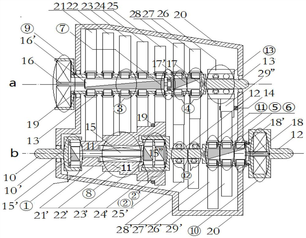
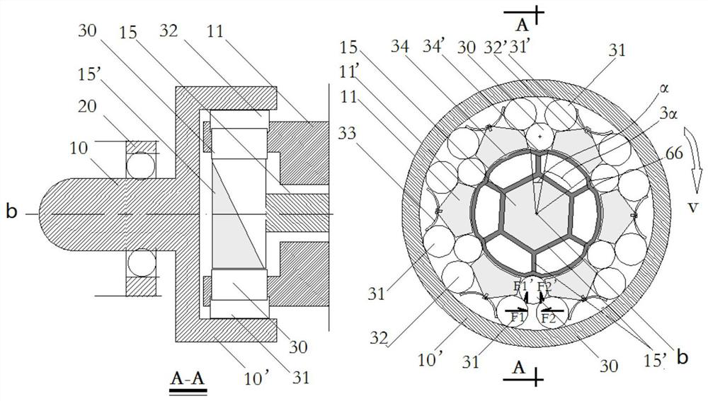
[0090] figure 1 Among them, ① and ⑥ on the b-axis are two-way electronically controlled roller lock-up clutches. Taking clutch ① as an example, the two-way electronically controlled roller lock-up clutch and its specific implementation are described.

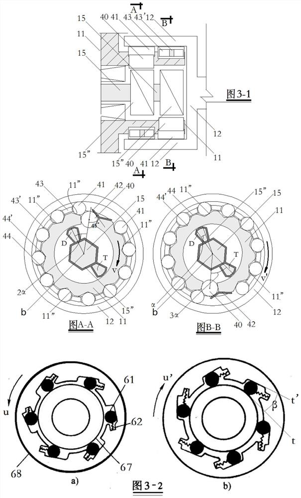
[0091] figure 1 , figure 2 Shown, the gearbox input shaft 10 and the sleeve shaft 10' are consolidated; the tower gear shaft 11 and the sleeve shaft 10' are the inner and outer rings of the electronically controlled roller lock-up clutch ①, that is, the two transmission parts of the clutch ①. Depend on figure 2 It can be seen that the two-way electronically controlled roller lock-up clutch ① consists of the outer ring 10', the inner ring 11, the lock rollers 31, 32 placed on the lock ramps 31', 32', and the rollers 31, 32 The tangential forced roller 30 and the locking ela...


PUM


Abstract

The invention discloses an electric control pin roller lock-up clutch combined by a speed picking cone pulley shaft and a transmission gear, and an electric control automatic gearbox. The automatic gearbox is a parallel shaft transmission mechanism and controls connection between an engine and a gearbox input shaft and connection between a gear output shaft and an automobile transmission shaft through the electric control pin roller lock-up clutch, input torque and output torque of the gearbox can be cut off according to needs, transmission of gears of the gearbox is avoided, and therefore abrasion of the gears can be reduced, and the service life of the gears is prolonged. The electronic control pin roller lock-up clutch composed of the speed picking cone pulley shaft, base gear outer gears and variable-pressure gear outer gears is controlled by an ECU via a servo motor in the speed picking cone pulley shaft, base gears and variable-pressure gears can be matched into multiple sets ofcomposite gears through a star row linkage device, and the output shaft is driven to rotate. According to a transmission mechanism, transmission wheels and shafts of the base gears and the variable-pressure gears are connected into a whole through the one-way electric control pin roller lock-up clutch or one-way bearing, so that the gears are switched smoothly, and transmission is continuous.

Description

[0001] Technical field [0002] The invention relates to a parallel shaft gearbox in the field of automobile machinery. Background technique [0003] The automatic transmissions in the prior art mostly implement the gear switching in the electro-hydraulic integration mode of controlling the hydraulic oil circuit by a solenoid valve; the transmission mechanism is mostly a hydraulic torque converter+planetary gear mechanism or+parallel shaft gear structure. [0004] Although the gearbox in the prior art can be intelligentized by controlling the electromagnetic valve through the ECU of the driving computer according to the running state and sensor data of the car, but the transmission efficiency, use or production cost are limited due to the control links and methods. Unsatisfactory. [0005] Automatic transmissions in the prior art are mainly divided into hydraulic automatic transmissions (AT), mechanical automatic transmissions (AMT), continuously variable automatic transmissi...

Claims


Application Information

Patent Timeline
IPC IPC(8): F16D45/00F16H63/34
CPCF16D45/00F16H63/34
Inventor 黄建
Owner 黄建
Learn More