
Efficient and environment-friendly industrial waste gas treatment and purification equipment

A technology for industrial waste gas and purification equipment, applied in lighting and heating equipment, incinerators, combustion methods, etc., can solve the problems of increasing the hidden danger of RTO purification equipment explosion, explosion of RTO purification equipment, accumulation of organic waste gas, etc., to save resources, Effect of improving mixing degree and preventing waste

Inactive Publication Date: 2020-11-03
刘景容
View PDF1 Cites 0 Cited by
  • Summary
  • Abstract
  • Description
  • Claims
  • Application Information

AI Technical Summary

Problems solved by technology

[0007] In order to make up for the deficiencies of the prior art, this invention proposes an efficient and environmentally friendly industrial waste gas treatment and purification equipment. When the concentration of organic matter is not within a level index, there will be a hidden danger of RTO purification equipment explosion. At the same time, when the organic waste gas in the preheating chamber is not fully preheated for a long time, it will lead to accumulation of organic waste gas, so that the concentration of waste gas will gradually increase. High, when the preheating chamber is in a state of high concentration for a long time, it will increase the explosion hazard of RTO purification equipment

Method used


Image

  • Efficient and environment-friendly industrial waste gas treatment and purification equipment
  • Efficient and environment-friendly industrial waste gas treatment and purification equipment
  • Efficient and environment-friendly industrial waste gas treatment and purification equipment

Examples


Embodiment approach

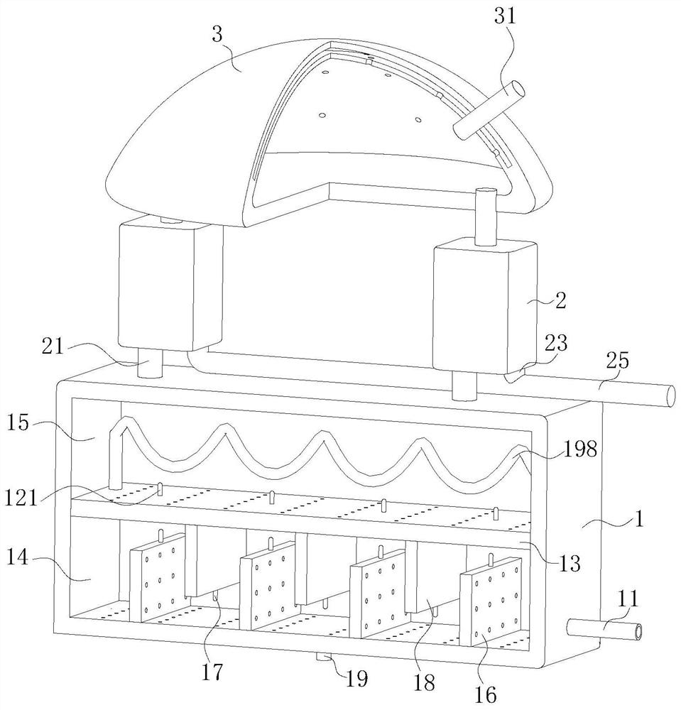
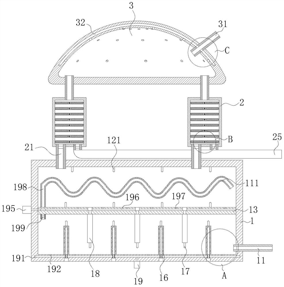
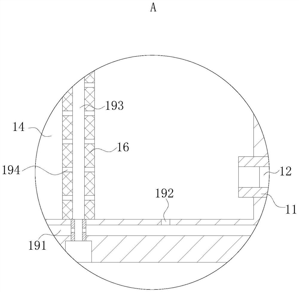
[0035] As an embodiment of the present invention, a second air pump 195 is fixedly connected to the left end surface of the detection box 1; a third air groove 196 is opened in the inner wall of the baffle plate 13, and the third air groove 196 is connected to the first The two air pumps 195 are in communication; the inner wall of the third air groove 196 is provided with uniformly arranged second through holes 197, and the second through holes 197 are all in communication with the upper cavity 15;

[0036] During work, since the third air groove 196 provided in the inner wall of the baffle plate 13 communicates with the second air pump 195, when the second concentration detector 121 detects that the concentration of the organic gas in the upper chamber 15 is too high, the controller will Control the operation of the second air pump 195. During the working process of the second air pump 195, the outside air can be sucked into the third air groove 196. When the gas flows into th...


PUM


Abstract

The invention belongs to the technical field of industrial waste gas treatment and purification equipment, and particularly relates to efficient and environment-friendly industrial waste gas treatmentand purification equipment. The equipment comprises a detection box, a preheating chamber and a combustion chamber. An air inlet pipe is fixedly connected into the inner wall of the right side of thedetection box; a baffle plate is fixedly connected in the inner wall of the detection box; a first auxiliary plate is rotationally connected into the inner wall of the bottom of the detection box through a motor; and the position, located in the inner wall of the baffle plate, of the lower surface of the baffle plate is rotationally connected with a second auxiliary plate through a motor. The equipment is mainly used for solving the hidden danger that existing RTO purification equipment can only purify waste gas with unified concentration or low concentration, and if the concentration of organic matter in the waste gas is not within one level index, the RTO purification equipment explodes, meanwhile, when the organic waste gas in the preheating chamber is not preheated completely for a long time, the organic waste gas can be stacked, the concentration of the waste gas is gradually increased, and when the preheating chamber is in a high-concentration state for a long time, the explosion hidden danger of RTO purification equipment can be increased.

Description

technical field [0001] The invention belongs to the technical field of industrial waste gas treatment and purification equipment, in particular to an efficient and environment-friendly industrial waste gas treatment and purification equipment. Background technique [0002] Waste gas treatment refers to the pretreatment of waste gas generated in industrial sites and factory workshops before being discharged to the outside, so as to meet the national standards for external discharge of waste gas. General waste gas treatment includes organic waste gas treatment, dust waste gas treatment, and acid-base waste gas treatment. , Odor waste gas treatment and air sterilization, disinfection and purification, etc., industrial waste gas treatment equipment is widely used in chemical plants, electronics factories, printing factories, painting workshops, painting factories, food factories, rubber factories, paint factories, petrochemical industries, etc. to generate dust, There are many t...

Claims


Application Information

Patent Timeline
Patent Type & Authority Applications(China)
IPC IPC(8): F23G7/06F23G5/08F23G5/44F23G5/50
CPCF23G5/08F23G5/44F23G5/50F23G7/06
Inventor 不公告发明人
Owner 刘景容
Learn More