Purifier water tank and purifier water tank cooling and purifying system
A purification system and purifier technology, applied in chemical instruments and methods, heat exchanger types, direct contact heat exchangers, etc., can solve the problem that the flammability of plant fibers is difficult to adapt, and achieve compact structure and good purification effect , good energy saving effect
- Summary
- Abstract
- Description
- Claims
- Application Information
AI Technical Summary
Problems solved by technology
Method used
Image
Examples
Embodiment 1
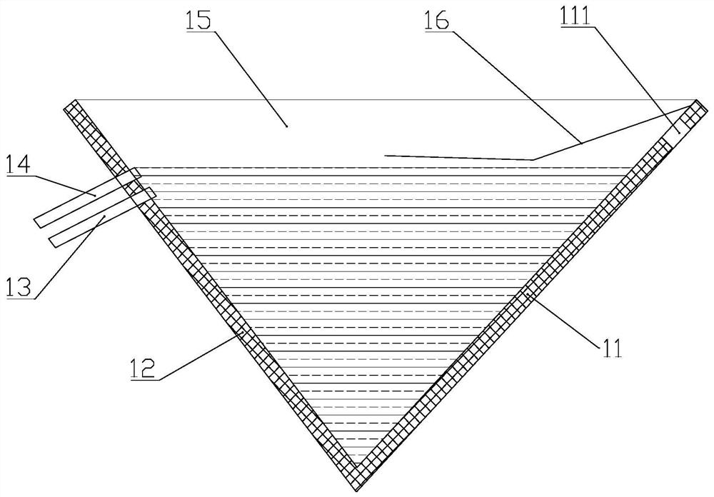
[0022] figure 1 A purifier tank according to an embodiment of the present invention is schematically shown.
[0023] refer to figure 1 The water tank of the purifier comprises a front side plate 11, a rear side plate 12, a water tank outlet pipe 13, a water tank overflow pipe 14, a side plate 15 and an airflow guide plate 16, and the lower end of the front side plate 11 is sealed with the lower end of the rear side plate 12 . One end of the water tank outlet pipe 13 is connected with the upper part of the rear side plate 12 and runs through the rear side plate 12 , and one end of the water tank overflow pipe 14 is connected with the upper part of the rear side plate 12 and runs through the rear side plate 12 . The connection position between the water tank outlet pipe 13 and the rear side plate 12 is lower than the connection position between the water tank overflow pipe 14 and the rear side plate 12 .
[0024] The side plate 15 is arranged as two pieces and is respectively...
Embodiment 2
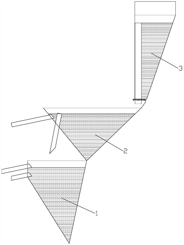
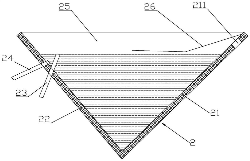
[0028] Figure 2 to Figure 5 A purifier water tank cooling and purifying system according to an embodiment of the present invention is schematically shown.
[0029] refer to Figure 2 to Figure 5 The purifier water tank cooling and purification system includes the above-mentioned purifier water tank 1 and a second cooling water tank 2 , and the second cooling water tank 2 is fixed above the purifier water tank 1 . The second cooling water tank 2 includes a second front side plate 21 , a second rear side plate 22 , and a second water tank outlet pipe 23 . The second water tank overflow pipe 24 , the second side plate 25 and the second airflow guide plate 26 . The lower end of the second front side plate 21 is sealingly connected with the lower end of the second rear side plate 22 . One end of the second water tank outlet pipe 23 is connected with the upper part of the second rear side plate 22 and passes through the second rear side plate 22, and one end of the second water ...
Embodiment 3
[0033] refer to figure 2 and Figure 4On the basis of Embodiment 2, a third cooling water tank 3 is also included, the third cooling water tank 3 is fixed above the second cooling water tank 2, and the third cooling water tank 3 includes a third front side plate 31 and a third rear side plate 32 , the third water tank outlet pipe 33 , the third side plate 34 and the third airflow guide plate 35 . The lower end of the third front side plate 31 is sealingly connected with the lower end of the third rear side plate 32, and the third side plate 34 is provided as two pieces and fixed on both sides of the third front side plate 31 and the third rear side plate 32 respectively. . A third vent 33 is disposed on an upper portion of the third front side panel 31 . One end of the third water tank outlet pipe 33 is connected to the top of the third rear side plate 32 and runs through the third rear side plate 32. The water output from the water tank outlet pipe 33 flows to the upper ...
PUM
 Abstract
Description
Claims
Application Information
 - R&D
- Intellectual Property
- Life Sciences
- Materials
- Tech Scout
- Unparalleled Data Quality
- Higher Quality Content
- 60% Fewer Hallucinations
Browse by: Latest US Patents, China's latest patents, Technical Efficacy Thesaurus, Application Domain, Technology Topic, Popular Technical Reports.
© 2025 PatSnap. All rights reserved.Legal|Privacy policy|Modern Slavery Act Transparency Statement|Sitemap|About US| Contact US: help@patsnap.com


