A gate drive circuit, drive method and display

A gate drive circuit and gate drive technology, used in static indicators, instruments, etc., can solve the problems of unsaturated charging, easy to appear stripe feeling, large cross voltage, etc., to reduce power consumption, increase power consumption, The effect of improving quality

Active Publication Date: 2021-11-09
HKC CORP LTD
View PDF5 Cites 0 Cited by
  • Summary
  • Abstract
  • Description
  • Claims
  • Application Information

AI Technical Summary

Problems solved by technology

The driving of the liquid crystal is related to the magnitude of the voltage. It needs positive and negative polarity inversion to apply voltage to drive the liquid crystal. The most commonly used polarity inversion method is dot inversion. The gate drive signal is transmitted row by row from one row to the last row to turn on the switching elements of each row in sequence. In order to cooperate with the inversion of the pixel electrode signal, the data signal is switched from positive polarity to negative polarity or from negative polarity to positive polarity at the moment of opening In one frame, for a dot inversion display panel composed of n rows of pixels, the data signal of each data line must be switched between positive and negative polarities n times, resulting in the existing dot inversion driving mode Although the display is uniform, the problem of high power consumption
According to different display screens, the same group of scanning lines in two adjacent rows is driven. Due to the large cross-voltage, bright and dark lines are prone to appear. Potential difference, resulting in insufficient charging time or unsaturated charging between rows with different polarities, so it is easy to guide the panel to display bright and dark lines
[0003] How to avoid the panel display prone to stripes and improve the quality of the display screen has become a problem that the industry attaches great importance to and affects the quality of the screen

Method used


Image

  • A gate drive circuit, drive method and display
  • A gate drive circuit, drive method and display
  • A gate drive circuit, drive method and display

Examples


Embodiment Construction

[0038] It should be understood that the terminology and specific structural and functional details disclosed herein are representative only for describing specific embodiments, but the application can be embodied in many alternative forms and should not be construed as merely Be limited by the examples set forth herein.

[0039]In the description of the present application, the terms "first" and "second" are used for descriptive purposes only, and cannot be understood as indicating relative importance, or implicitly indicating the quantity of indicated technical features. Therefore, unless otherwise specified, the features defined as "first" and "second" may explicitly or implicitly include one or more of these features; "plurality" means two or more. The term "comprising" and any variations thereof mean non-exclusive inclusion, possible presence or addition of one or more other features, integers, steps, operations, units, components and / or combinations thereof.

[0040] Als...


PUM


Abstract

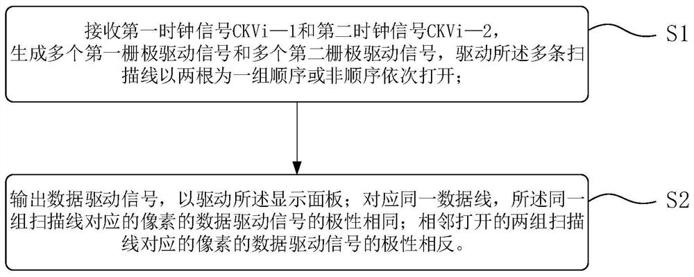
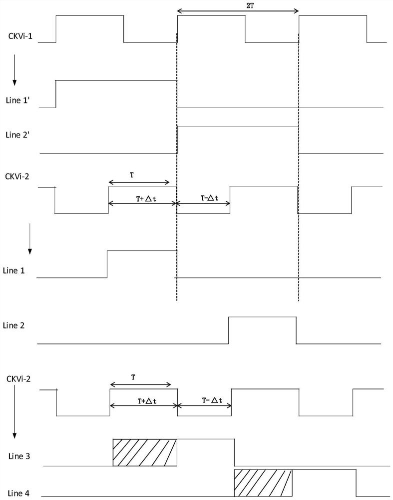
The present application discloses a gate drive circuit, a drive method, and a display. The drive method of the gate drive circuit includes the following steps: receiving a first clock signal and a second clock signal, and generating a plurality of first gate drive signals and a plurality of second gate driving signals to drive a plurality of scanning lines to scan and charge in a group of two sequentially or non-sequentially; output data driving signals to drive the display panel; corresponding to the same data line, the same group of scanning The polarities of the data drive signals of the pixels corresponding to the lines are the same; the polarities of the data drive signals of the pixels corresponding to the two groups of adjacent scanning lines are opposite; the first clock signal is a square wave signal with a cycle of 2T, so The second clock signal is a square wave signal with a period of 2T, and the falling edge of the second clock signal is at the same moment as the rising edge of the first clock signal; the charging efficiency between rows with different polarities is compensated to improve display quality.

Description

technical field [0001] The present application relates to the field of display technology, in particular to a gate drive circuit, method and display. Background technique [0002] The driving of the liquid crystal display is to adjust the applied signal to establish a driving electric field according to the phase, peak value, frequency, etc. of different signals, so as to realize the effect of liquid crystal deflection display screen. The driving of the liquid crystal is related to the magnitude of the voltage. It needs positive and negative polarity inversion to apply voltage to drive the liquid crystal. The most commonly used polarity inversion method is dot inversion. The gate drive signal is transmitted row by row from one row to the last row to turn on the switching elements of each row in sequence. In order to cooperate with the inversion of the pixel electrode signal, the data signal is switched from positive polarity to negative polarity or from negative polarity to ...

Claims


Application Information

Patent Timeline
Patent Type & Authority Patents(China)
IPC IPC(8): G09G3/36
CPCG09G3/3677G09G2310/0281G09G3/20G09G2310/027G09G2310/0278G09G2310/0291G09G2310/08
Inventor 郭东胜袁海江顾毓波
Owner HKC CORP LTD
Why Eureka
Try Eureka