Smart bracelet with health monitoring function
A smart bracelet and health monitoring technology, applied in diagnostic recording/measurement, medical science, sensors, etc., can solve problems such as the tightness of straps that cannot be taken off for cleaning, and achieve accuracy improvement, high accuracy, and prevent service life shortened effect
- Summary
- Abstract
- Description
- Claims
- Application Information
AI Technical Summary
Problems solved by technology
Method used
Image
Examples
Embodiment 1
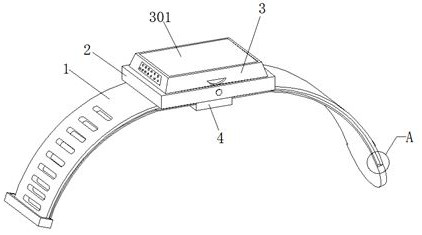
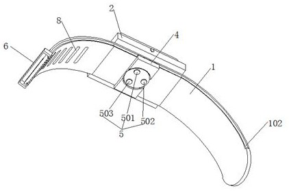
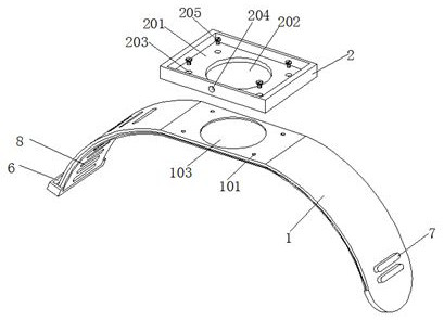
[0033] Embodiment 1 introduces a kind of smart bracelet with health monitoring function, refer to the attached figure 1 , attached figure 2 , attached image 3 , attached Figure 4 And attached Figure 5 , its main structure includes an integrally formed wristband 1 and a main body casing 2, the upper surface of the main body casing 2 is provided with a main body snap-in groove 201, and the center of the bottom wall of the main body snap-in groove 201 is provided with a round hole 202, which is located in the circle A threaded connection hole 203 is provided on the bottom wall of the main engine snap-in groove 201 around the hole 202 . The host body 3 is snapped into the slot 201 of the host, and the inside of the host body 3 is provided with a microprocessor (not shown in the figure), a storage device (not shown in the figure) and a main battery (not shown in the figure). ), the upper surface of the main body 3 is provided with a micro-display 301, the lower surface of t...
Embodiment 2
[0041] Embodiment 2 is a further improvement made on the basis of Embodiment 1, below in conjunction with the attached Figure 1~9 explain it further.
[0042] Embodiment 2 discloses an improved smart bracelet with health monitoring function based on Embodiment 1. Refer to the attached figure 1 , attached figure 2 , attached image 3 , attached Figure 4 And attached Figure 5 , its main structure includes an integrally formed wristband 1 and a main body casing 2, the upper surface of the main body casing 2 is provided with a main body snap-in groove 201, and the center of the bottom wall of the main body snap-in groove 201 is provided with a round hole 202, which is located in the circle A threaded connection hole 203 is provided on the bottom wall of the main engine snap-in groove 201 around the hole 202 . The host body 3 is snapped into the slot 201 of the host, and the inside of the host body 3 is provided with a microprocessor (not shown in the figure), a storage de...
PUM
 Abstract
Description
Claims
Application Information
 - R&D
- Intellectual Property
- Life Sciences
- Materials
- Tech Scout
- Unparalleled Data Quality
- Higher Quality Content
- 60% Fewer Hallucinations
Browse by: Latest US Patents, China's latest patents, Technical Efficacy Thesaurus, Application Domain, Technology Topic, Popular Technical Reports.
© 2025 PatSnap. All rights reserved.Legal|Privacy policy|Modern Slavery Act Transparency Statement|Sitemap|About US| Contact US: help@patsnap.com


