Construction waste soil material recycling device

A technology of recycling device and construction waste, applied in the direction of solid separation, filter screen, grille, etc., can solve the problems of low economic benefit and pollute the environment, and achieve the effect of improving economic benefit and convenient recycling.

Active Publication Date: 2020-11-06
徽川建设有限公司
View PDF5 Cites 1 Cited by
  • Summary
  • Abstract
  • Description
  • Claims
  • Application Information

AI Technical Summary

Problems solved by technology

[0004] The purpose of the present invention is to provide a recycling device for construction waste and soil materials that can automatically crush and screen construction waste, effectively recycle metal waste and soil materials, improve economic benefits, and reduce environmental pollution. Garbage is simply stacked or buried, with low economic benefits and environmental pollution

Method used


Image

  • Construction waste soil material recycling device
  • Construction waste soil material recycling device
  • Construction waste soil material recycling device

Examples


Embodiment 1

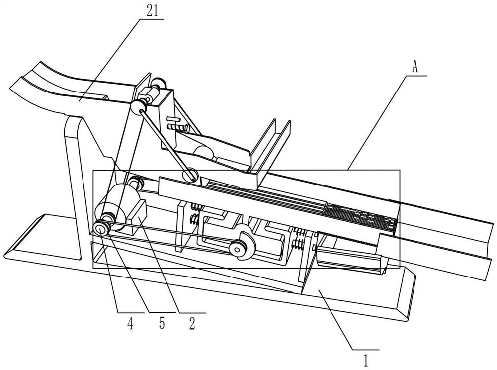
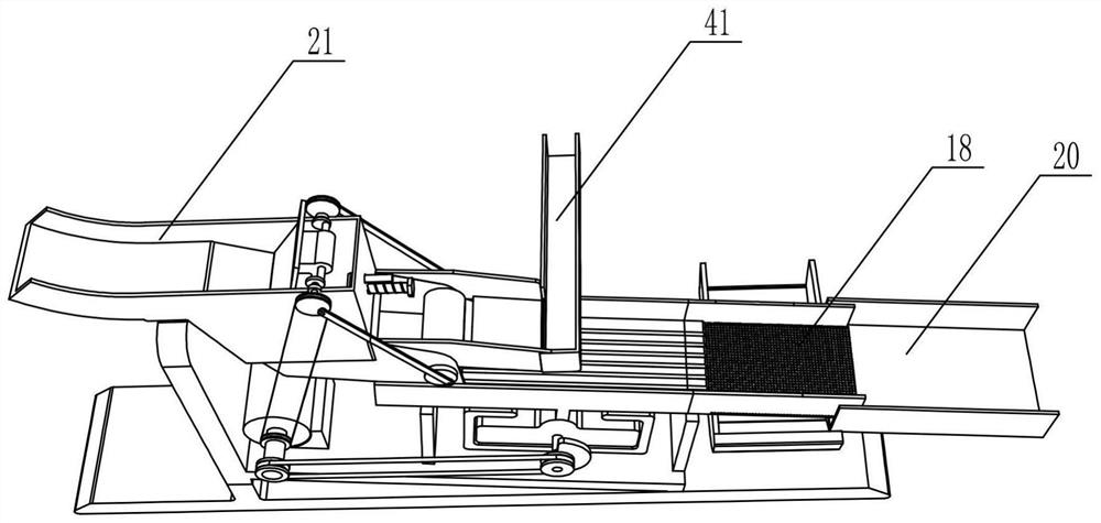
[0025] Such as Figure 1-Figure 8 As shown, a construction waste earth material recovery device includes a base 1, a clamp block 2, a biaxial motor 3, a rotating shaft 4, a pulley 5, a vibration mechanism, a conveying frame 17, a screen 18, and a feeding frame 19 And the material receiving frame 20, the clamp block 2 that plays a supporting role is fixedly installed on the base 1, and the biaxial motor 3 that plays a driving role is fixedly installed on the clamp block 2 and is close to the base 1. The rotating shaft-4 of the transmission effect is respectively fixedly installed on the two output ends of the biaxial motor 3 and arranged symmetrically. The vibrating mechanism is installed on the base 1, the conveying frame 17 that plays a role in transmission is fixedly installed on the vibrating mechanism, and the screening net 18 that can screen out fine soil materials is fixedly installed on the right end of the conveying frame 17, and the described screen used for receiving...

Embodiment 2

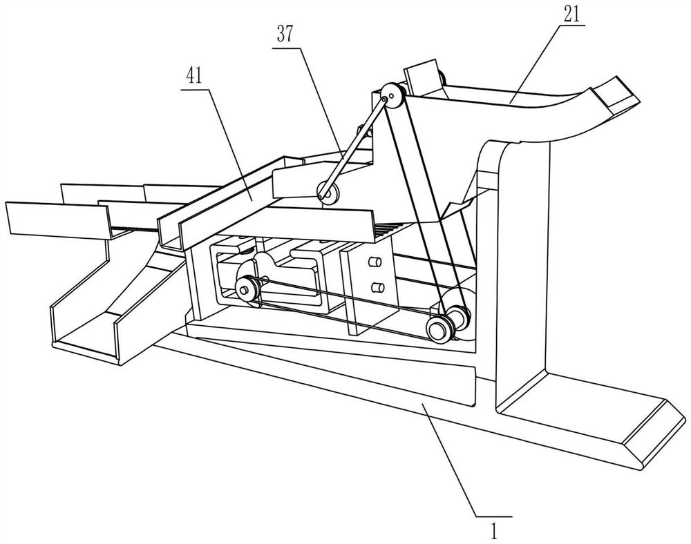
[0031] On the basis of Example 1, such as Figure 1-Figure 8 As shown, it also includes a screening mechanism that can screen out metal waste. The screening mechanism includes a rotating disk 2 36, a connecting rod 37, a magnet ring 38, a fixed plate 39, a scraper 40 and a material protection frame 41, and the two rotating disk 2 36 are respectively fixedly installed on the front and rear ends of the rotating shaft 4 35 and are close to the guardrail frame 34. The lower ends of the two connecting rods 37 that play a transmission role are respectively connected in a rotational manner with the two rotating discs 2 36 through the tip rods, and the upper ends are connected through the tip rods. It is connected with pulley three 23 side rotation, and the magnetic magnet ring 38 is fixedly installed on the rotating shaft four 35 and between the two guardrail frames 34, and the fixed plate 39 that plays a fixed role is fixedly installed on the On the two guardrail frames 34 and close...


PUM


Abstract

The invention discloses a construction waste soil material recycling device. The construction waste soil material recycling device comprises a base, a clamping block, a double-shaft motor, first rotating shafts, a first belt wheel, a vibrating mechanism, a conveying bracket and the like. The clamping block is fixedly mounted on the base. The double-shaft motor is fixedly mounted on the clamping block. The two first rotating shafts are fixedly mounted at two output ends of the double-shaft motor correspondingly. The vibrating mechanism is mounted on the base. The conveying bracket is fixedly mounted on the vibrating mechanism. Screening net is fixedly mounted at one end of the conveying bracket. A discharging bracket is fixedly mounted on the base. A material receiving bracket is fixedly mounted on the discharging bracket and is in contact with the screening net. By means of a screening mechanism arranged on the construction waste soil material recycling device, metal waste high in recovery value in construction waste can be screened out in advance, and economic benefits of recycling of the construction waste are increased; and by means of the vibrating mechanism, the crushed construction waste can be automatically conveyed rightwards, a soil material is screened out through the screening net, and the soil material can be recycled conveniently.

Description

technical field [0001] The invention relates to the technical field of garbage recovery, in particular to a device for recovering construction waste earth materials. Background technique [0002] Construction waste refers to the general designation of muck, waste concrete, waste masonry and other waste generated in the production activities of people engaged in demolition, construction, decoration, repair and other construction industries. According to the classification of generation sources, construction waste can be divided into engineering slag Soil, decoration waste and demolition waste, etc.; classified by composition, construction waste can be divided into muck, concrete blocks, crushed stones, brick and tile fragments, waste mortar and scrap metal. [0003] At present, most cities only simply deal with construction waste, and generally adopt open-air stacking and simple burial. The site selection for stacking and burial is also largely random, leaving many safety haz...

Claims


Application Information

Patent Timeline
Patent Type & Authority Applications(China)
IPC IPC(8): B02C1/04B02C1/10B02C23/08B02C23/16B07B1/28
CPCB02C1/04B02C1/10B02C23/08B02C23/16B02C2023/165B02C2201/06B07B1/28
Inventor 汪汉荣
Owner 徽川建设有限公司
Why Eureka
Try Eureka