
Eye-brow shaping blade set welding machine and machining process thereof

A technology of blade set and welding machine, which is applied in metal processing equipment, welding equipment, manufacturing tools, etc., can solve problems such as welding of blades and mesh sleeves that have not been described, and achieve the goal of promoting production efficiency, improving automation, and promoting bending Effect

Pending Publication Date: 2020-11-06
万里溪
View PDF0 Cites 0 Cited by
  • Summary
  • Abstract
  • Description
  • Claims
  • Application Information

AI Technical Summary

Problems solved by technology

[0004] Although the overall structure achieves the stamping of the blade, it does not describe the welding of the blade and the mesh, and the focus of the production of the eyebrow trimming knife is the combination of the blade and the mesh. Therefore, there is an urgent need for a welding machine for eyebrow trimming blades and its processing technology

Method used


Image

  • Eye-brow shaping blade set welding machine and machining process thereof
  • Eye-brow shaping blade set welding machine and machining process thereof
  • Eye-brow shaping blade set welding machine and machining process thereof

Examples


Embodiment 1

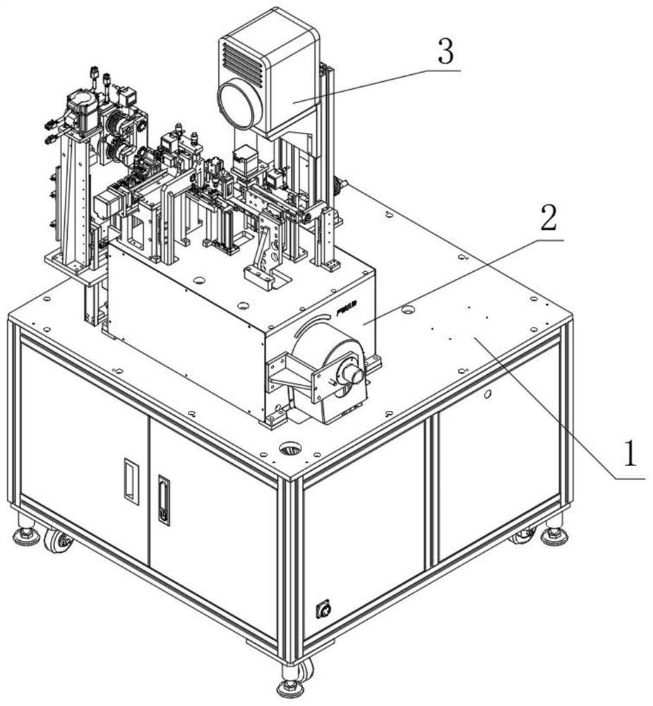
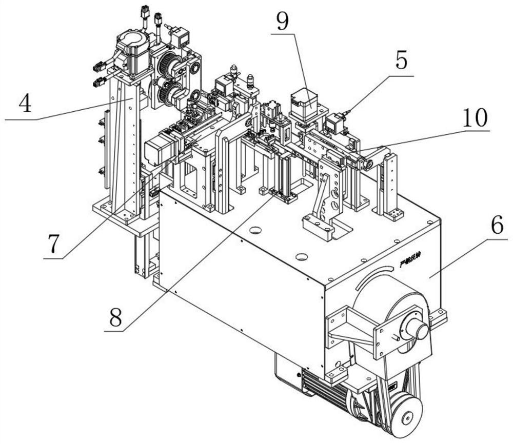
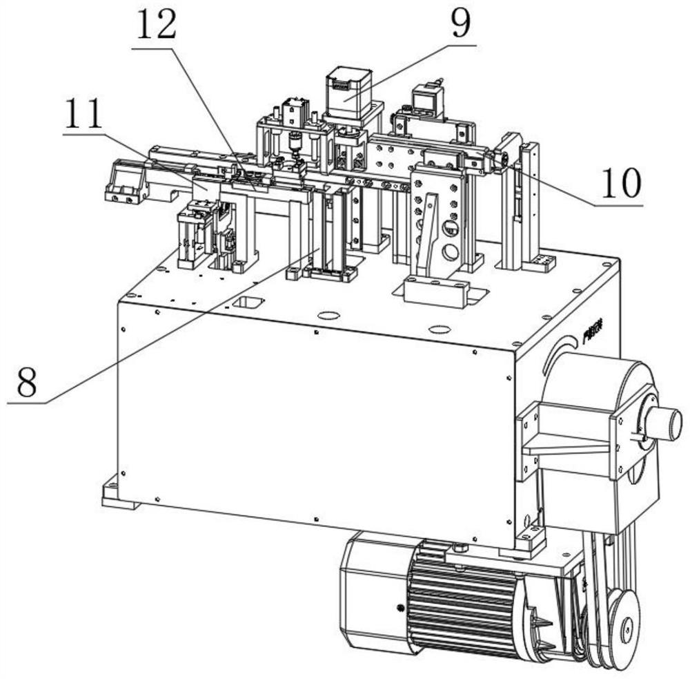
[0042] A kind of eyebrow trimming blade group welding machine, such as figure 1 Shown: includes a frame 1, a host 2 and a laser welding lens 3, the top outer wall of the frame 1 is fixed with a host 2 by bolts, and one side of the outer wall of the host 2 is fixed with a laser welding lens 3 by bolts, the host 2, such as figure 2 image 3 Shown: including material receiving mechanism 4, main working assembly 5, power distribution box 6, blade silo 7 and mesh sheet silo 8, said main working assembly 5, such as figure 2 image 3 As shown: it includes a mesh sheet feeding mechanism 9, a stepping mechanism 10, a working channel 12, a combination of a blade distribution die and a mesh sheet bending upper die 23, and a clamping and welding mechanism 11. The receiving mechanism 4 is fixed on the On one side of the top of the frame 1, the outer wall of the top of the frame 1 has mounting holes, and the power distribution box 6 is fixed in the mounting holes by bolts, and each com...

Embodiment 2

[0054] In this embodiment, on the basis of Embodiment 1, the processing technology of the eyebrow trimming blade in the welding machine is set forth, including the following steps:

[0055] S1: Push the net cover sheet 34 to the first working position 15 of the working channel 12 through the feeding mechanism 9;

[0056] S2: Push the mesh sheet 34 on the first working position 15 to the second working station 14 through the push rod 19, and the upper mold 24 for bending the mesh sheet and the lower mold 16 for bending the mesh sheet are attached to each other Bending the mesh sheet 34 in a manner;

[0057] S3: Push the bent mesh sheet 34 on the second working station 14 to the third working station 13 through the push rod 19; The mold delivery 26 pushes the blade 33 of the blade magazine 7 into the bent net cover sheet 34 on the third working position 13, and then clamps the rear clamp 29 of the front clamp 28 of the clamp welding mechanism 11 on the locking block 30 Move to...


PUM


Abstract

The invention discloses an eye-brow shaping blade set welding machine and a machining process thereof. The equipment set welding machine comprises a rack, a main engine and a laser welding lens. The main engine is arranged on the outer wall of the top of the rack, and the laser welding lens is arranged on the outer wall of one side of the main engine. The main engine comprises a collecting mechanism, a main work assembly, a power distributing box, a blade bin and a net sleeve sheet bin. The main work assembly comprises a net sleeve sheet supply mechanism, a stepping mechanism, a work channel,a blade distributing mold and net sleeve sheet bending upper mold assembly and a clamping and welding mechanism. The collecting mechanism is arranged on one side of the top of the rack, and a mountinghole is formed in the outer wall of the top of the rack. The power distributing box is arranged in the mounting hole, and all assemblies of the main work assembly are arranged at the top of the powerdistributing box. According to the eye-brow shaping blade set welding machine and the machining process thereof, the dredging and combining work of blades and net sleeve sheets is completed, the automation degree of eye-brow shaping blade machining is greatly improved, mechanization of eye-brow shaping blade producing and machining is improved, and the production efficiency is promoted.

Description

technical field [0001] The invention relates to the technical field of processing eyebrow trimming blades, in particular to an eyebrow trimming blade assembly welding machine and a processing technology thereof. Background technique [0002] Eyebrows can outline the shape of the face and change the structure of the face. But the distribution of small eyebrows is messy, and because they are thin and short, eyebrow pliers can't do anything about them, so you need the help of an eyebrow trimmer. It can help repair, gently leave no traces, the knife edge has a protective effect, and will not hurt the skin. In the production and processing of the eyebrow trimming blade, it is necessary to effectively process the blade and the net cover, and make them clamp and weld. [0003] The prior art discloses a stamping die for eyebrow trimming knife, which includes an upper cover plate, an upper mold base, a lower template, an upper splint, a stripper plate, a lower template and a lower ...

Claims


Application Information

Patent Timeline
IPC IPC(8): B23K26/21B23K26/70
CPCB23K26/21B23K26/702
Inventor 万里溪
Owner 万里溪
Learn More