Rotatable gear machining and polishing device

A technology of gears and rotating rods, which is applied in the direction of grinding drive devices, machine tools designed for grinding the rotating surface of workpieces, metal processing equipment, etc., and can solve the problems of inability to meet the needs of gear grinding, poor adjustment flexibility, and inconvenient use. , to achieve the effects of improving practicability, facilitating control and reducing costs

Active Publication Date: 2020-11-06
WENZHOU UNIVERSITY
View PDF6 Cites 5 Cited by
  • Summary
  • Abstract
  • Description
  • Claims
  • Application Information

AI Technical Summary

Problems solved by technology

[0004] The purpose of the present invention is to solve the disadvantages of poor adjustment flexibility in the prior art, troublesome operation, and inability to meet the needs of grinding gears with different apertures, resulting in very inconvenient use, and proposes a rotatable gear Processing and grinding device

Method used


Image

  • Rotatable gear machining and polishing device
  • Rotatable gear machining and polishing device
  • Rotatable gear machining and polishing device

Examples


Embodiment 1

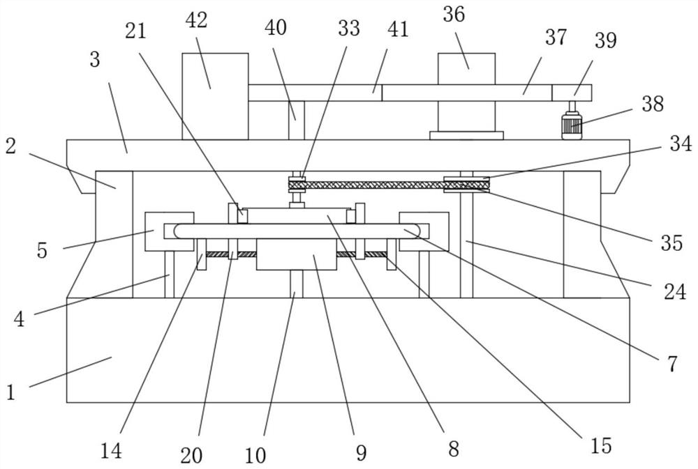
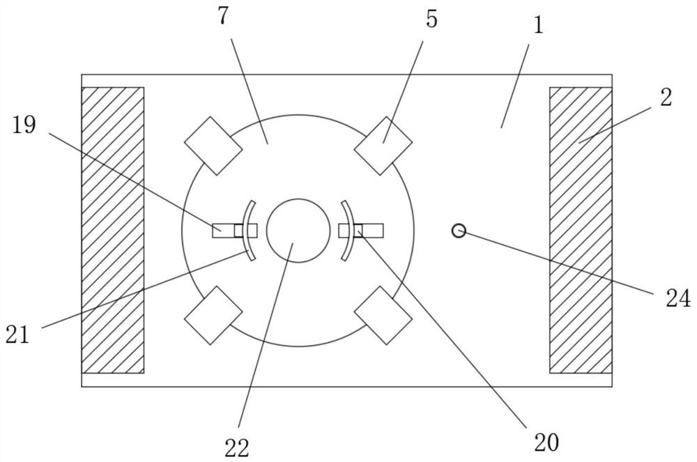
[0033] refer to Figure 1-9 , a rotatable gear processing and grinding device, comprising a base 1, the base 1 is a hollow structure, two vertical plates 2 are fixedly connected symmetrically to both sides of the top outer wall of the base 1, and the tops of the two vertical plates 2 are fixedly connected to the same The top plate 3 and the base 1 are fixedly connected with four lifting cylinders 4, and the four lifting cylinders 4 are arranged in a square, and the tops of the four lifting cylinders 4 all extend to the top of the base 1 and are fixedly connected with lifting blocks 5. The sides of each lifting block 5 that are close to each other are provided with grooves 6, and the same circular plate 7 is slidably connected in the four grooves 6, and a processing gear 8 is movably placed at the center of the top of the circular plate 7, and the top of the circular plate 7 A circular groove 22 is provided at the center of the circle, and two sets of clamping assemblies for cl...

Embodiment 2

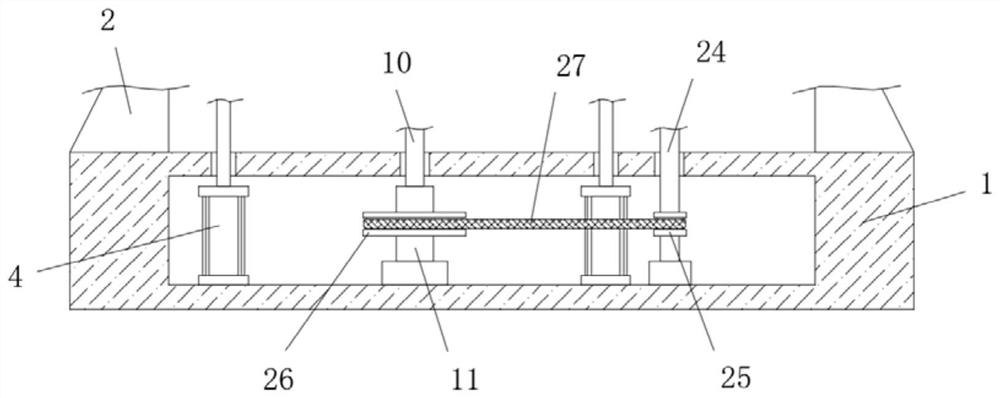
[0035] Further improved on the basis of Embodiment 1: the rotating assembly includes a slide bar 10 fixedly connected to the outer wall of the bottom of the square block 9, one side of the slide bar 10 extends to the inside of the base 1 and a sleeve 11 is slidably sleeved on the sleeve. The bottom end of 11 is connected with the bottom inner wall of the base 1 in rotation, and the rotation of the sleeve 11 drives the slide bar 10 to rotate, which can drive the square block 9 to rotate, and then drives the circular plate 7 to rotate. The inner wall of the sleeve 11 is annularly provided with multiple Draw-in slot 12, one side outer wall of slide bar 10 is annularly provided with a plurality of draw-in strips 13, and a plurality of draw-in bars 13 are slidably connected in a plurality of draw-in grooves 12 respectively, through the cooperation of draw-in bar 13 and draw-in groove 12, when When the sleeve 11 rotates, it can drive the slide bar 10 to rotate. The two groups of clam...


PUM


Abstract

The invention belongs to the technical field of gear machining, particularly discloses a rotatable gear machining and polishing device, and puts forward the following scheme so as to solve the problemof gear machining and polishing devices are very inconvenient to use due to the fact that the gear machining and polishing devices are poor in adjustment flexibility, are troublesome to operate and cannot meet polishing requirements of gears in different hole diameters in the prior art. The rotatable gear machining and polishing device comprises a base; the base is of a hollow structure; two vertical plates are symmetrically and fixedly connected on the two sides of the outer wall of the top of the base; and the tops of the two vertical plates are fixedly connected with a same top plate. According to the rotatable gear machining and polishing device, the height of a round plate can be adjusted by the aid of lifting air cylinders, the clamping effect on machining gears can be achieved through starting of a first servo motor, the machining gears and a polishing roller can be driven simultaneously to perform synchronous operation through starting of a driving motor, the requirement for polishing the machining gears in different hole diameters can be realized under the condition that normal work of the polishing roller is not affected through starting of a second servo motor, and thusthe machining and polishing efficiency is improved.

Description

technical field [0001] The invention relates to the technical field of gear processing, in particular to a rotatable gear processing and grinding device. Background technique [0002] A gear is a mechanical element with teeth on the wheel rim that can continuously mesh and transmit motion and power. It is a mechanical part with teeth that can mesh with each other. The application of gears in transmission has appeared very early. The successive emergence of special machine tools and cutting tools for gear cutting has provided more complete means for gear processing, and with the development of production, the stability of gear operation has been paid more attention. [0003] When the existing gear processing and grinding device grinds the inner ring of the gear, the grinding device not only has poor adjustment flexibility, but also is troublesome to operate, and cannot meet the needs of grinding gears with different apertures, which makes it very inconvenient to use. Therefor...

Claims


Application Information

Patent Timeline
Patent Type & Authority Applications(China)
IPC IPC(8): B24B5/08B24B41/02B24B41/06B24B47/12B24B47/22
CPCB24B5/08B24B41/02B24B41/067B24B47/12B24B47/22
Inventor 潘晓铭张玉朋林晋豪瞿建武潘敏辉陈益丰
Owner WENZHOU UNIVERSITY
Why Eureka
Try Eureka