Alternating-current low-voltage power distribution cabinet

A power distribution cabinet, low-voltage technology, applied in the field of AC low-voltage power distribution cabinets, can solve the problems of large noise, loud noise, looseness and other problems of power distribution cabinets, achieve stability assurance, improve processing effects, and reduce noise effects

Inactive Publication Date: 2021-06-04
汪知义
View PDF1 Cites 4 Cited by
  • Summary
  • Abstract
  • Description
  • Claims
  • Application Information

AI Technical Summary

Problems solved by technology

[0005] In order to overcome the above-mentioned defects of the prior art, the present invention provides an AC low-voltage power distribution cabinet. The technical problem to be solved by the present invention is: when the power distribution cabinet is in operation, because the internal power equipment often generates relatively large noise, Moreover, it is difficult to carry out coordinated operation when cooling it through electrical facilities such as wind power. The use of multiple electrical equipment tends to increase the burden on the operation of the internal equipment of the power distribution cabinet, which often causes the power distribution cabinet to emit light during use. Larger noise, and larger vibrations will be emitted during the operation of the internal equipment of the power distribution cabinet, which will not only easily cause damage due to vibration, but also cause loose connections between the internal equipment of the power distribution cabinet The problem

Method used


Image

  • Alternating-current low-voltage power distribution cabinet
  • Alternating-current low-voltage power distribution cabinet
  • Alternating-current low-voltage power distribution cabinet

Examples


Embodiment Construction

[0029] The following will clearly and completely describe the technical solutions in the embodiments of the present invention with reference to the accompanying drawings in the embodiments of the present invention. Obviously, the described embodiments are only some, not all, embodiments of the present invention. Based on the embodiments of the present invention, all other embodiments obtained by persons of ordinary skill in the art without making creative efforts belong to the protection scope of the present invention.

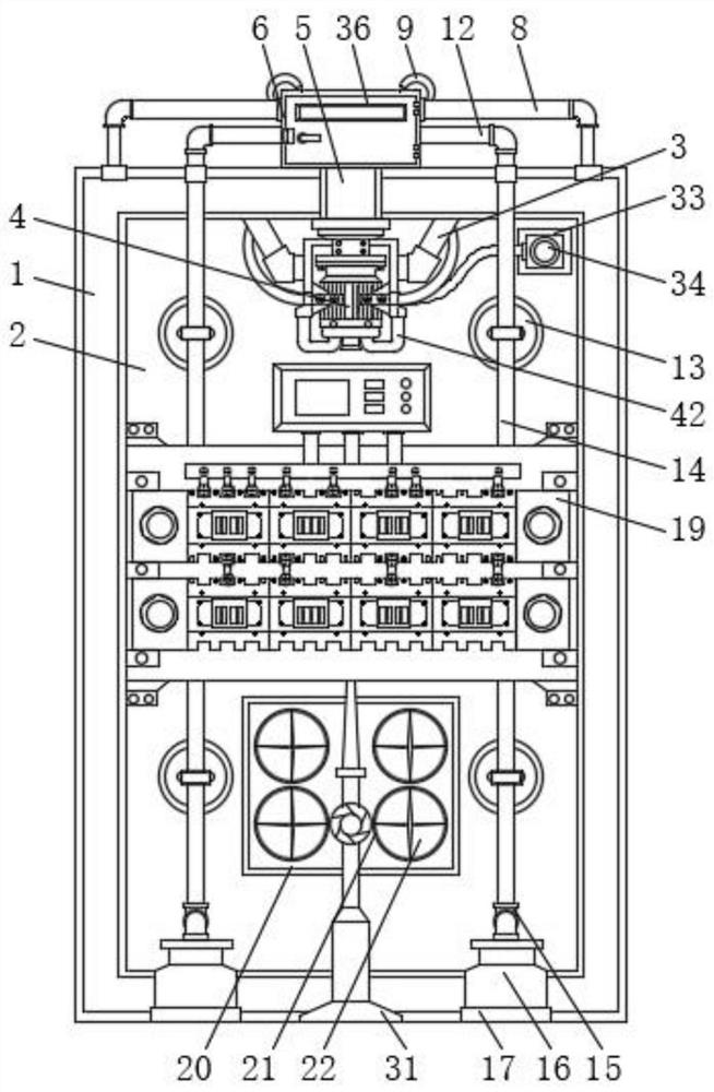
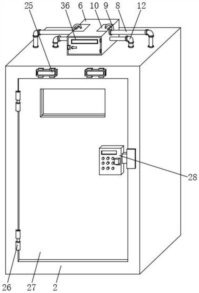
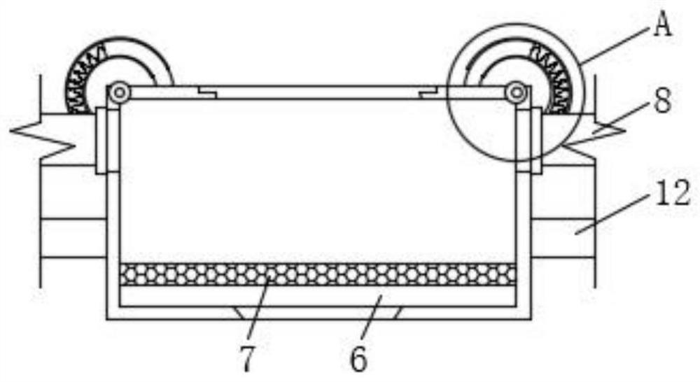
[0030] Such as Figure 1-9 As shown, the present invention provides an AC low-voltage power distribution cabinet, including a first protective shell 1, the inner wall of the first protective shell 1 is fixedly connected with the outer surface of the second protective shell 2, and the upper surface of the inner wall of the second protective shell 2 It is fixedly connected with the top of the support frame 3, and the support frame 3 is provided with an air pump ...


PUM


Abstract

The invention discloses an alternating-current low-voltage power distribution cabinet, and particularly relates to the technical field of power distribution cabinets, the alternating-current low-voltage power distribution cabinet comprises a first protective shell, the inner wall of the first protective shell is fixedly connected with the outer surface of a second protective shell, the upper surface of the inner wall of the second protective shell is fixedly connected with the top end of a supporting frame, and an air pump is arranged in the supporting frame. According to the power distribution cabinet, by arranging the air pump, the back plate suction cup and the bottom plate suction cup, after the cabinet door plate of the power distribution cabinet is closed, the space of the first protection shell and the space of the second protection shell can form a space similar to vacuum due to air shortage, and therefore it is guaranteed that sound generated in the operation process of the power distribution cabinet is not likely to be transmitted to the outside, the noise processing effect of the power distribution cabinet is improved, and when the air pump operates, the back plate suction cups and the bottom plate suction cups can also play a role in fixing the power distribution cabinet, so that the stability of the power distribution cabinet during operation is guaranteed, and the situation that equipment in the power distribution cabinet shakes or topples over due to operation is reduced.

Description

technical field [0001] The invention relates to the technical field of power distribution cabinets, and more specifically, the invention relates to an AC low-voltage power distribution cabinet. Background technique [0002] The power distribution cabinet (box) is divided into power distribution cabinet (box), lighting distribution cabinet (box), metering cabinet (box), and is the final equipment of the power distribution system. The cabinet is used in the occasions where the load is relatively scattered and there are few circuits; the motor control center is used in the occasions where the load is concentrated and there are many circuits. They distribute the electric energy of a certain circuit of the upper-level power distribution equipment to the nearby load. The load provides protection, monitoring and control. [0003] Chinese patent literature (CN201510111695.5) discloses an AC low-voltage power distribution cabinet, which states in the specification that "AC low-volta...

Claims


Application Information

Patent Timeline
Patent Type & Authority Applications(China)
IPC IPC(8): H02B1/30H02B1/54H02B1/56H02B1/32H02B1/16
CPCH02B1/16H02B1/30H02B1/303H02B1/32H02B1/54H02B1/565
Inventor 汪知义
Owner 汪知义
Why Eureka
Try Eureka