

Grinding equipment for hardware machinery fitting processing
A technology of mechanical parts and equipment, which is applied in the field of grinding equipment for processing hardware machinery parts, can solve problems such as low work efficiency, incomplete grinding, and potential safety hazards, and achieve the effects of improving grinding efficiency, improving fixing effect, and increasing water spray pressure
- Summary
- Abstract
- Description
- Claims
- Application Information
AI Technical Summary
Problems solved by technology
Method used
Image

Examples
Embodiment 1
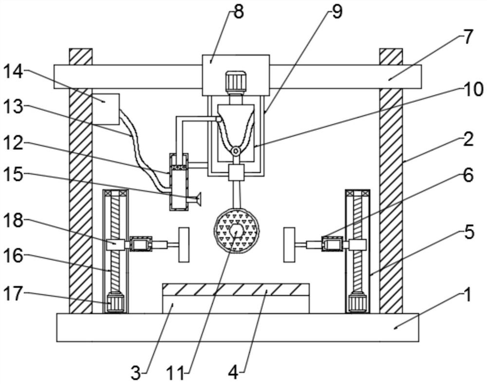
[0025] see figure 1 , in an embodiment of the present invention, a kind of grinding equipment for processing hardware and mechanical parts, slide bars 2 are fixedly installed on both sides above the base 1, a workbench 3 is arranged at the center of the base 1, and the workbench 3 is surface-mounted There are anti-slip pads 4, fixed columns 5 are arranged on both sides of the workbench 3, and a fixing device 6 is arranged on the side of the fixed column 5 close to the workbench 3; The middle part of the support plate 7 is provided with an electric slide 8, and a transmission chamber 9 is provided below the electric slide 8, and a lifting device 10 is arranged in the transmission chamber 9, and a grinding plate 11 is fixedly connected to the bottom of the lifting device 10, One side of the transmission bin 9 is fixedly connected with a water spray pipe 12 through a pole, one side of the water spray pipe 12 is connected with a water pipe 13, and the other end of the water pipe 1...
Embodiment 2
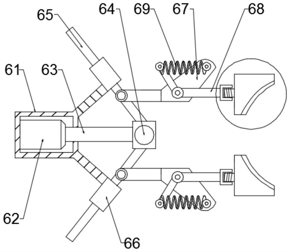
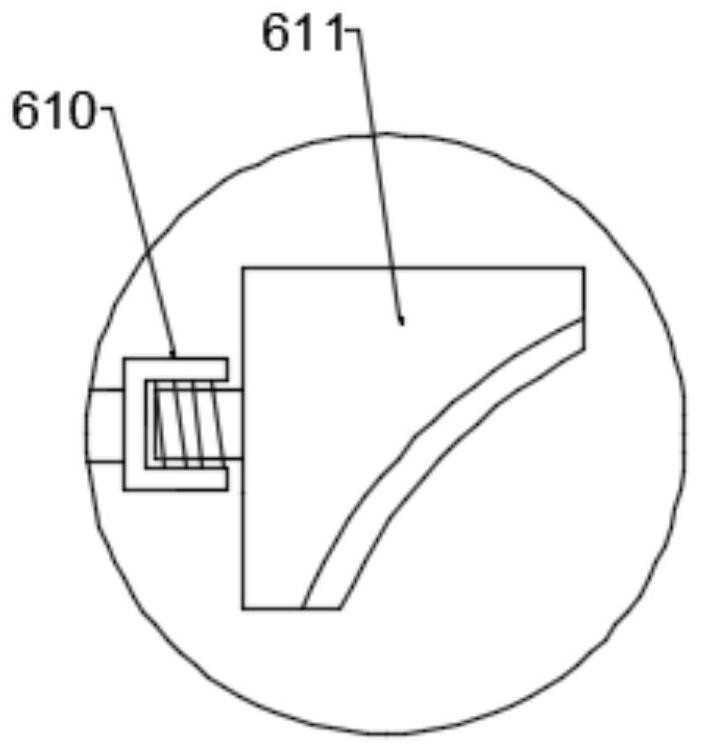
[0028] see figure 2 with image 3 , in this embodiment, the fixing device 6 includes a driving chamber 61, a hydraulic machine base 62 is arranged inside the driving chamber 61, and a hydraulic rod 63 is connected to the hydraulic machine base 62, and a hinge seat is installed at the end of the hydraulic rod 63 64, the upper and lower sides of the hinge seat 64 are symmetrically hinged with movable rods 65, the upper and lower sides of the drive bin 61 are fixedly connected with sleeves 66, the movable rods 65 slide inside the sleeves 66, and the lower part of the movable rods 65 is horizontal A fixed seat 67 is fixedly connected, and an L-shaped connecting rod 68 is hinged on the fixed seat 67. A compression spring 69 is connected between one end of the L-shaped connecting rod 68 and the fixed seat 67. The other end of the L-shaped connecting rod 68 One end is fixedly connected with a connection block 610, and the connection block 610 is connected with a fixed plate 611, an...
Embodiment 3
[0031] see Figure 4 , in this embodiment, the lifting device 10 includes a cylindrical cam 101, a second drive motor 102 is connected above the cylindrical cam 101, and a first transmission rod 103 is slidably connected in a chute on the surface of the middle part of the cylindrical cam 101, so The first transmission rod 103 is connected with a lifting rod 104, the bottom of the lifting rod 104 is connected with the grinding plate 11, and the rotation of the second drive motor 102 drives the cylindrical cam 101 to rotate. When the cylindrical cam 101 rotates, the chute on the surface and the The first transmission rod 103 cooperates to realize the up and down movement of the lifting rod 104, thereby driving the grinding plate 11 to grind up and down intermittently, which improves the grinding effect on the workpiece.
[0032] In this embodiment, the elevating rod 104 is set through the transmission chamber 9, and a limit sleeve 105 is provided at the joint between the elevati...
PUM
 Abstract
Description
Claims
Application Information