Transferring device, robot, sorting system and sorting method

A technology of transfer device and sorting system, which is applied in the directions of sorting, storage, transportation and packaging, and can solve the problems of low working efficiency of robots

Pending Publication Date: 2020-11-06
HAI ROBOTICS CO LTD
View PDF9 Cites 14 Cited by
  • Summary
  • Abstract
  • Description
  • Claims
  • Application Information

AI Technical Summary

Problems solved by technology

[0004] However, when the robot is unloading, it needs to move the turnover boxes on each storage shelf out of the body one by one through the pick-up device, resulting in low working efficiency of the robot

Method used


Image

  • Transferring device, robot, sorting system and sorting method
  • Transferring device, robot, sorting system and sorting method
  • Transferring device, robot, sorting system and sorting method

Examples


Embodiment 1

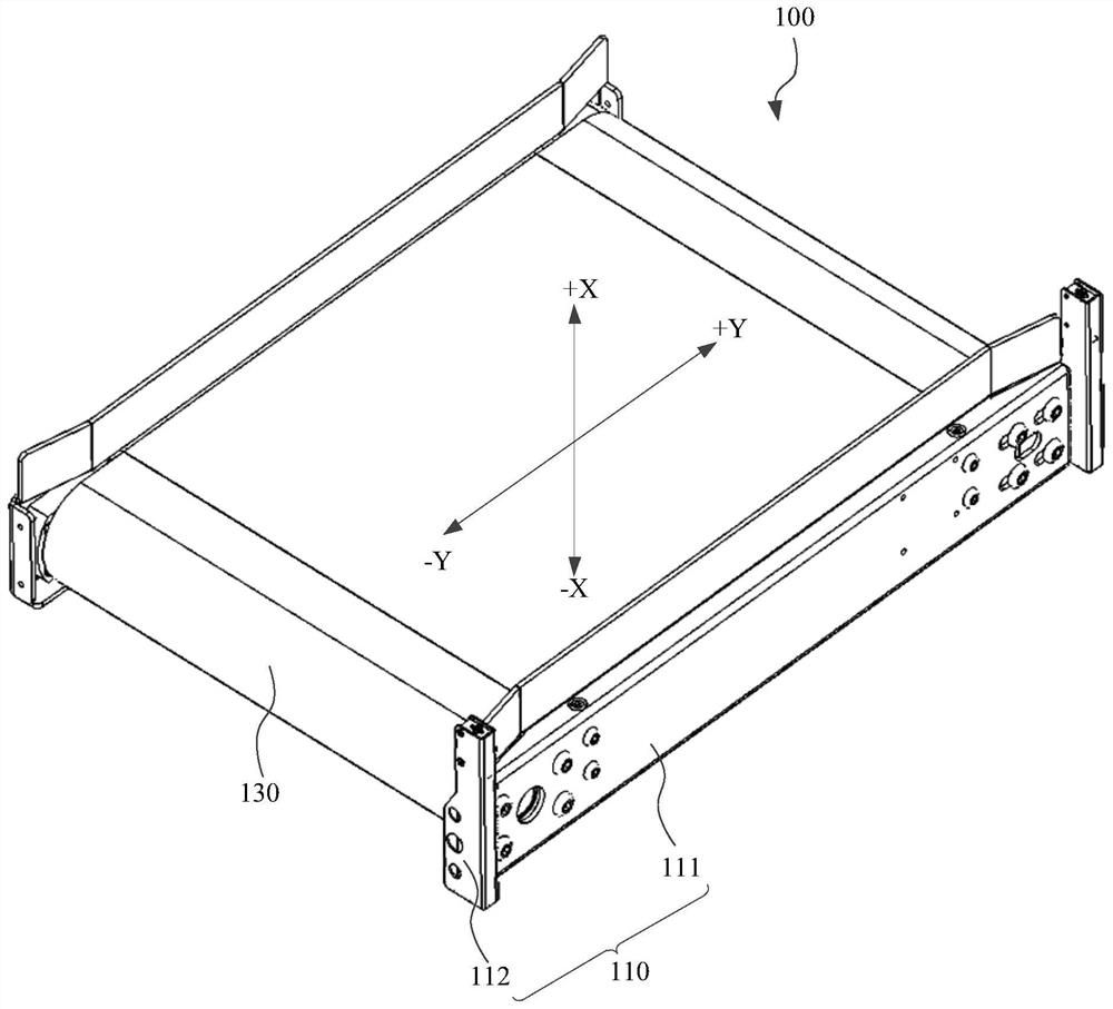
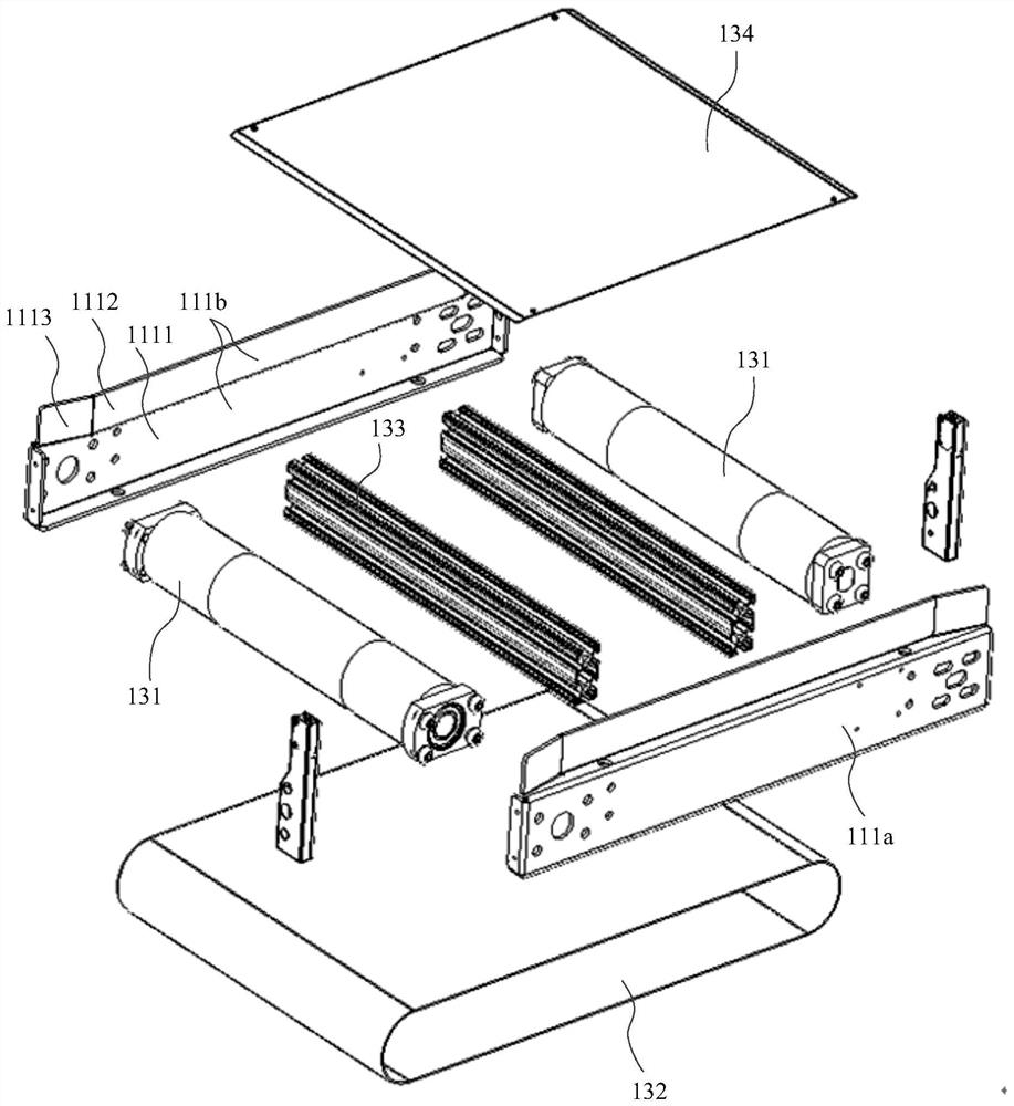
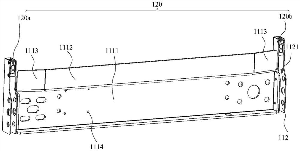
[0108] figure 1 A schematic structural diagram of the transport device provided in the embodiment of the present disclosure; figure 2 An exploded view of the transport device provided by the embodiment of the present disclosure; image 3 A schematic structural diagram of the stent and the detection assembly in the transport device provided in the embodiment of the present disclosure; Figure 4 A schematic structural diagram of a support rod in the transport device provided by the embodiment of the present disclosure; Figure 5 A use state diagram of the transport device provided by the embodiment of the present disclosure; Image 6 for Figure 5 top view of ; Figure 7 A schematic structural diagram of a robot provided by an embodiment of the present disclosure; Figure 8 for Figure 7 Partial enlarged view at A. see Figure 1 to Figure 8 As shown, the present disclosure provides a transfer device 100, which is applied to a device in which a multi-layer turnover box 2...

Embodiment 2

[0135] please continue Figure 1 to Figure 8 As shown, the present disclosure also provides a robot 300, including a body 310 and at least one transfer device 100 disposed on the body 310, where the transfer device 100 is the transfer device 100 provided in any of the above embodiments.

[0136] The structure of the transport device 100 has been described in detail in the above embodiments, and will not be repeated here.

[0137] A pick-up device may also be provided on the robot 300 , and the pick-up device is used to transport the turnover box 200 to the transfer device 100 . Wherein, the pickup device may be a commonly used pickup device, such as a robotic arm, a gripping fork, or a clamping claw, which is not limited in the present disclosure. of this embodiment Figure 7 In the description, the fork 313 is taken as the pickup device.

[0138] In order to facilitate the movement of the robot 300, in a specific implementation, the body 310 includes a first mobile chassis...

Embodiment 3

[0146] Figure 9 Schematic diagram of the structure of the sorting system provided by the embodiment of the present disclosure Figure 1 . see Figure 1 to Figure 9 As shown, the sorting system provided by the present disclosure includes at least one conveyor 400 and at least one robot 300 provided in the above-mentioned embodiments. The conveyor 400 is used to receive the turnover box 200 on the robot 300, or to transfer the turnover box 200 on the conveyor 400. The box 200 is transferred to the robot 300 .

[0147] The structure of the robot 300 has been described in detail in the above embodiments, and will not be repeated here.

[0148] In the following, possible implementation structures of the conveyor 400 will be described through different embodiments.

[0149] Figure 10 Schematic diagram of the structure of the conveyor in the sorting system provided by the embodiment of the present disclosure Figure 1 ; Figure 11 for Figure 10 Schematic diagram of the int...


PUM


Abstract

The invention provides a transferring device, a robot, a sorting system and a sorting method. The transferring device is applied to equipment on which multiple layers of circulating boxes can be arranged in the first direction. At least two layers of transferring devices are arranged in the first direction of the equipment. The transferring device comprises a supporting base and a first transmission assembly. The first transmission assembly is located on the supporting base. The first transmission assembly transports the circulating boxes. According to the transferring device, the working efficiency of the equipment can be improved.

Description

technical field [0001] The present disclosure relates to the field of intelligent storage, and in particular to a transfer device, a robot, a sorting system and a sorting method. Background technique [0002] Intelligent warehousing is an important link in the logistics process. Robots can replace manual handling of turnover boxes and play an important role in intelligent warehousing. [0003] The robot includes a body, a control device arranged on the body, a picking device and a plurality of storage shelves, and the movement of the body is controlled by the control device. The revolving box on the storage shelf is moved out of the main body (also called loading) or placed on the storage shelf on the main body (also called unloading) by the pick-up device. [0004] However, when the robot is unloading, it needs to move the turnover boxes on each storage shelf out of the main body one by one through the pick-up device, resulting in low working efficiency of the robot. Co...

Claims


Application Information

Patent Timeline
Patent Type & Authority Applications(China)
IPC IPC(8): B65G1/04B07C3/02
CPCB65G1/04B07C3/02B07C5/36B65G1/0407B65G1/0421B07C2501/0063B65G1/06B07C3/08B65G1/0435
Inventor 陈叶广
Owner HAI ROBOTICS CO LTD
Why Eureka
Try Eureka