
Anti-winding mechanism for end face fibers of textile machinery rotating parts

A technology of rotating parts and textile machinery, applied in the field of textile fiber processing, can solve the problems of easy loosening and slipping of fibers, laborious operation, easy wear of drum hinges, etc., and achieve the effect of reducing the effect

Active Publication Date: 2020-11-06
泉州联兴发针织织造有限公司
View PDF11 Cites 1 Cited by
  • Summary
  • Abstract
  • Description
  • Claims
  • Application Information

AI Technical Summary

Problems solved by technology

[0007] In order to solve the above technical problems, the present invention provides a fiber winding anti-winding mechanism on the end surface of the rotating part of the textile machine to solve the problem that the self-locking structure of the hinge connection of the drum support frame is poor when the existing fiber winding mechanism is in use, and the hinges are mostly Self-locking will be achieved by increasing friction. Frequent disassembly of the drum hinges is easy to wear, the self-locking effect is reduced, and it is easy to loosen and slip when the fiber is entangled. It is laborious to operate; The blade cuts off the fiber, and the blade will generate a large friction force when it rotates. After the fiber is cut off, it will stop working, and the fiber needs to be reconnected with the drum. When the drum is disassembled and installed, the clamping effect of the joint of the drum is poor, and the drum There will be a gap on one side, and the fiber will easily enter the gap and get entangled

Method used


Image

  • Anti-winding mechanism for end face fibers of textile machinery rotating parts
  • Anti-winding mechanism for end face fibers of textile machinery rotating parts
  • Anti-winding mechanism for end face fibers of textile machinery rotating parts

Examples


Embodiment

[0038] as attached figure 1 to attach Figure 11 Shown:

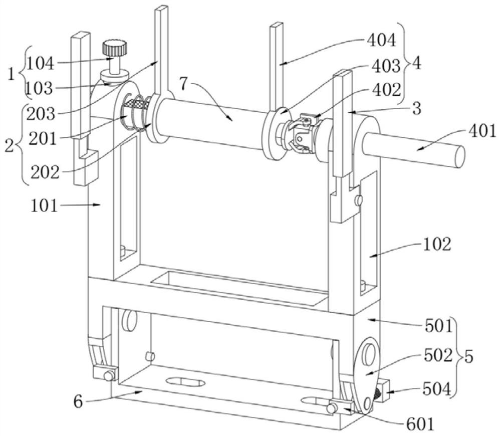
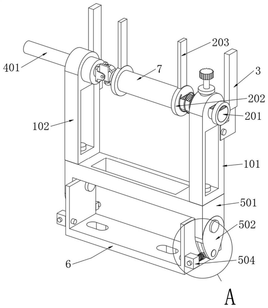
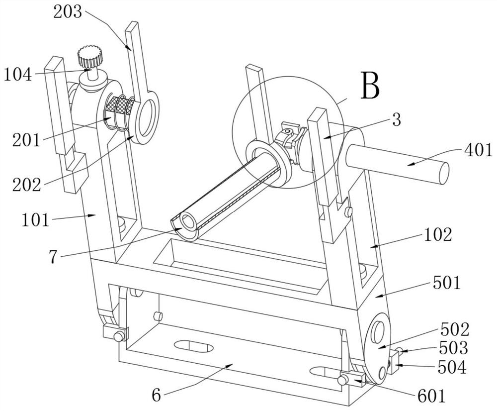
[0039] The present invention provides an end face fiber anti-winding mechanism for rotating parts of textile machinery, which includes a support mechanism 1; a rectangular hole for reducing weight is opened on the support mechanism 1, and an elastically connected clamping mechanism 2 is installed on the support mechanism 1 to clamp A pull ring is installed on the mechanism 2; the support mechanism 1 includes a support plate A101, a support plate B102, a nut placement seat 103 and a clamping bolt 104, and the bottoms of the support plate A101 and the support plate B102 are processed with rectangular blocks, and the U-shaped support The seat 501 is symmetrically provided with two limiting grooves matching with the rectangular block, and one side of the supporting plate A101 and the supporting plate B102 are provided with limiting grooves matching the handle 3, and the supporting plate A101 is provided with a nut placemen...


PUM


Abstract

The invention provides an anti-winding mechanism for end face fibers of textile machinery rotating parts. The anti-winding mechanism comprises a supporting mechanism. A rectangular hole for reducing weight is formed in the supporting mechanism. The supporting mechanism is provided with a clamping mechanism in an elastic mode. A pulling ring is installed on the clamping mechanism. Two T-shaped handles are fixed on the supporting mechanism through bolts. Rubber sleeves sleeve the handles. The supporting mechanism is provided with a rotating mechanism in a rotary mode. And the rotating mechanismis connected with a power mechanism. According to the anti-winding mechanism for the end face fibers of the textile machinery rotating parts, clamping and anti-winding structures of a roller are improved. Through a sliding rod A installed on a supporting plate A in an elastic mode, the sliding rod A can slide inward to clamp the roller. Through a clamping bolt installed on the supporting plate A,the sliding rod A can be clamped and fixed by the clamping bolt. Through a grooving installed on an end cover A, the roller can be effectively hided by the grooving. The groove on the end cover A canblock fiber lines and reduce the winding effect of fibers.

Description

technical field [0001] The invention belongs to the technical field of textile fiber processing, and more specifically relates to an end face fiber anti-winding mechanism of a rotary part of a textile machine. Background technique [0002] Textile fibers are divided into two types: natural fibers and chemical fibers. Flax, cotton yarn, hemp rope, etc. are obtained from plants and belong to natural fibers. During textile processing, the fibers will be wound through the drum. During the actual operation of the drum, often appear The phenomenon of fiber entanglement, in recent years, new high-strength fine fiber raw materials have emerged continuously, and the fiber entanglement between the rotating parts of textile machinery and equipment and the rotating rod makes manual cleaning difficult and reduces the production efficiency of textiles. [0003] For example, the existing Chinese utility model patent with the patent number CN201920668236.0 discloses a fiber anti-winding mec...

Claims


Application Information

Patent Timeline
Patent Type & Authority Applications(China)
IPC IPC(8): B65H54/04B65H54/70B65H54/72D01G9/16F16D63/00
CPCB65H54/04B65H54/72B65H54/70D01G9/16F16D63/006
Inventor 郑浩南
Owner 泉州联兴发针织织造有限公司
Learn More