
Voltage controlled oscillator and non-contact IC card with voltage controlled oscillator

A technology of voltage-controlled oscillators and oscillating signals, which is applied to record carriers used in machines, instruments, and automatic power control. It can solve problems such as unstable oscillations and VCO inability to oscillate, and achieve the effect of reducing current consumption.

Inactive Publication Date: 2003-08-20
MITSUBISHI ELECTRIC CORP +1
View PDF1 Cites 0 Cited by
  • Summary
  • Abstract
  • Description
  • Claims
  • Application Information

AI Technical Summary

Problems solved by technology

That is, it may happen that both points B and E are stable at H level, and the VCO cannot oscillate.
[0014] Since the conventional voltage-controlled oscillator is configured as above, when it is used in an application that has the possibility of stopping the operation when the charge remains on both capacitors 220 and 320 and restarting in this state, there is a problem that it cannot be used. The subject of stable oscillation

Method used


Image

  • Voltage controlled oscillator and non-contact IC card with voltage controlled oscillator
  • Voltage controlled oscillator and non-contact IC card with voltage controlled oscillator
  • Voltage controlled oscillator and non-contact IC card with voltage controlled oscillator

Examples


Embodiment Construction

[0039] Embodiments of the present invention will be described below.

[0040] Embodiment 1

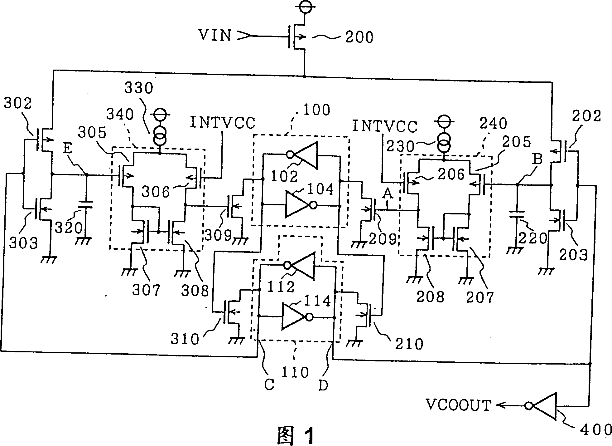
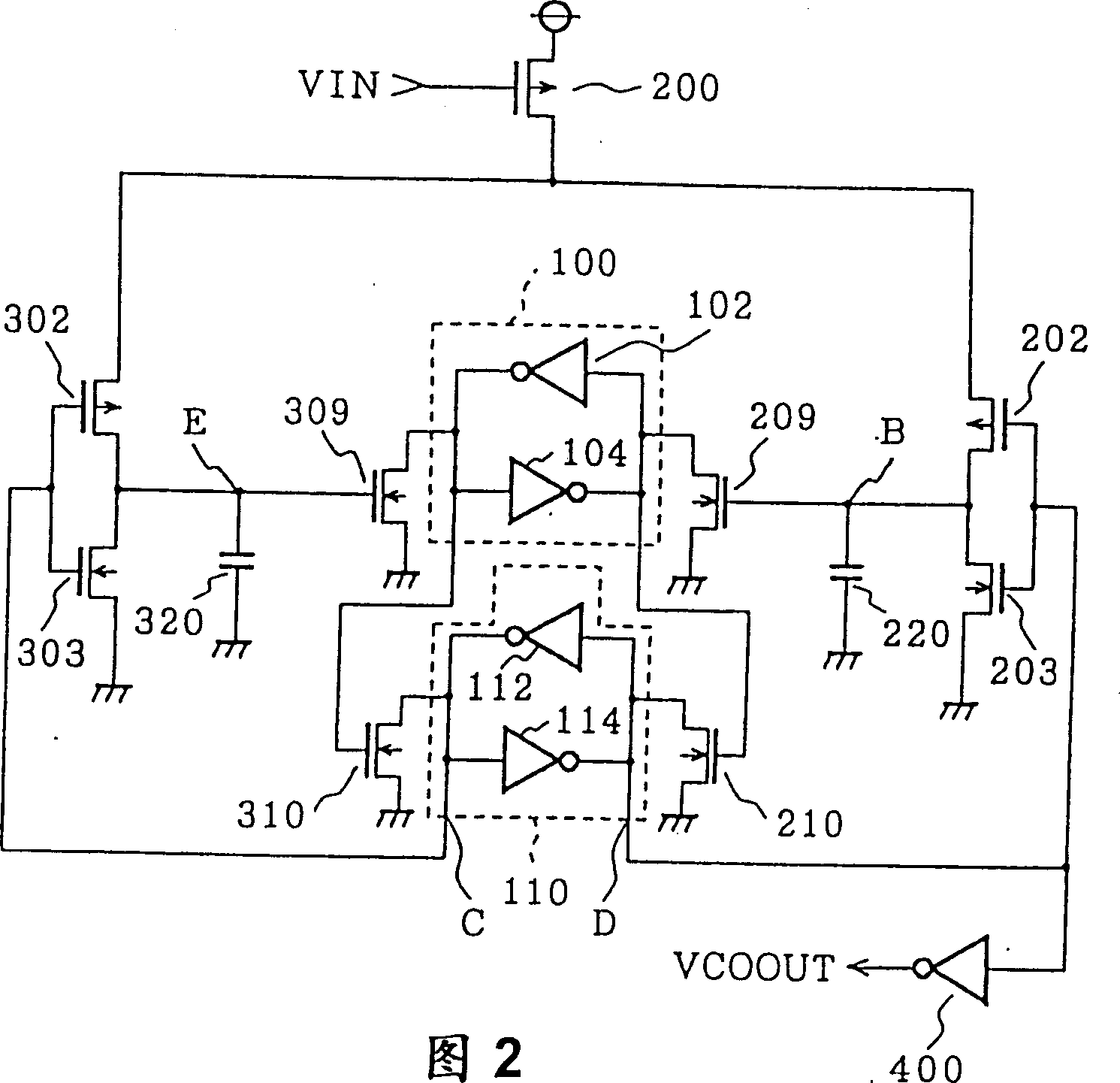
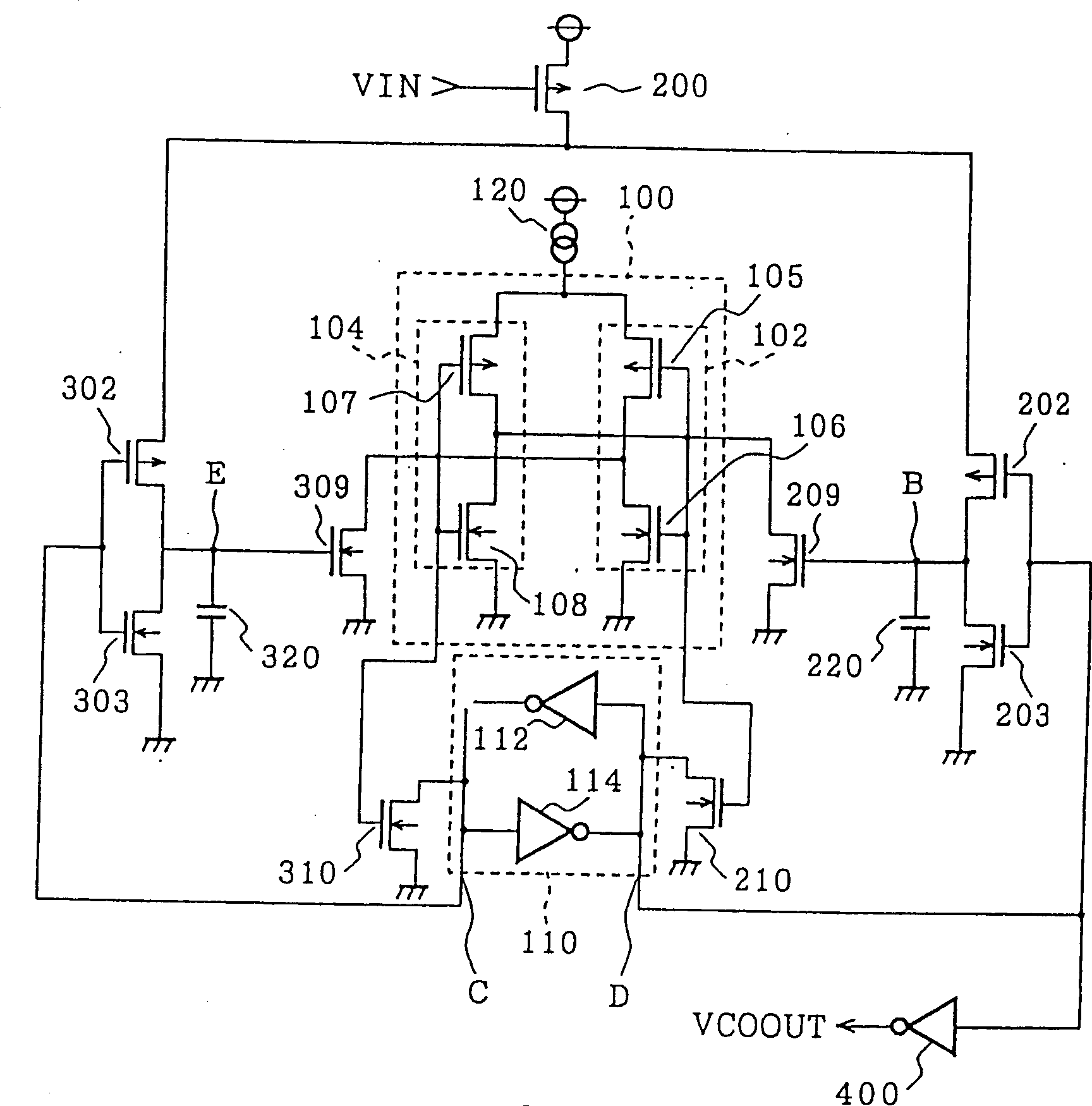
[0041] Fig. 1 is a circuit diagram showing the configuration of a voltage-controlled oscillator according to Embodiment 1 of the present invention. In the figure, 110 is a latch circuit (second storage device) composed of two inverter circuits 112 and 114, and 210 is an N-channel transistor, one of the latch circuit (first storage device) 100 is connected to its gate. The output terminal 310 is an N-channel transistor, the gate of which is connected to the other output terminal of the latch circuit 100 . The drain of the N-channel transistor 210 becomes one input terminal of the latch circuit 110 , and the drain of the N-channel transistor 310 becomes the other input terminal of the latch circuit 110 . Other structural elements are the same as those shown in FIG. 9 . In this case, the level of one output point D of the latch circuit 110 is supplied to the gate of the P-channel trans...


PUM


Abstract

To stop a voltage-controlled oscillator while charges are left in both capacitors and to prevent the oscillator from oscillating when the oscillator is restarted front the stopping state. Even when a voltage-controlled oscillator (VCO) is started while charges are left in capacitors 220 and 320, both N-channel transistors 209 and 309 are turned on, because the outputs of both differential circuits 240 and 340 are at high levels. Since the gate of the VCO is connected to the drains of the transistors 209 and 309, both N-channel transistors 210 and 310 are turned off. Therefore, the levels at both output points C and D of a latch circuit 110 do not become lower at the same time.

Description

technical field [0001] The invention relates to a voltage-controlled oscillator whose oscillation signal frequency varies with input voltage and a non-contact IC card with the voltage-controlled oscillator. Background technique [0002] FIG. 9 is a circuit diagram showing the configuration of a conventional voltage-controlled oscillator (VCO). In the figure, 100 is a latch circuit composed of two inverting circuits 102 and 104, 200 is a P-channel transistor, its gate is supplied with an input voltage VIN, its source is supplied with a power supply voltage such as 5V, and 202 is a P-channel Transistor, its source is connected to the drain of P channel transistor 200, 203 is an N channel transistor, its drain is connected to the drain of P channel transistor 202, the source is grounded, 220 is a capacitor, one end of which is connected to P channel transistor The drain of 202 and the drain of N-channel transistor 203, the other end is grounded, 230 is a constant current circu...

Claims


Application Information

Patent Timeline
Patent Type & Authority Patents(China)
IPC IPC(8): G06K19/07G06K19/073H03K3/014H03K3/03H03K3/354H03L7/00
CPCG06K19/073G06K19/0701G06K19/0723H03K3/354H03K3/014H03K3/03H03L7/00
Inventor 松原利之
Owner MITSUBISHI ELECTRIC CORP
Learn More