
Marine oil pollution recovery device

A technology of oil pollution recovery and inflatable device, which is applied in general water supply conservation, water conservancy projects, and cleaning of open water surfaces, etc. It can solve the problems of limited capacity of oil-absorbing felt, limited oil absorption efficiency, and low efficiency of oil removal, etc., and achieves simple structure and good High efficiency of separation and oil pollution

Active Publication Date: 2020-11-06
TIANJIN RES INST FOR WATER TRANSPORT ENG M O T
View PDF5 Cites 1 Cited by
  • Summary
  • Abstract
  • Description
  • Claims
  • Application Information

AI Technical Summary

Problems solved by technology

[0003] Some existing offshore oil pollution recovery devices use oil-absorbing felt to absorb oil. Although it is a more feasible solution, after all, the capacity of oil-absorbing felt is limited, and the oil-absorbing efficiency is limited. Too much seawater leads to low efficiency of oil removal, and requires secondary separation of oil and seawater

Method used


Image

  • Marine oil pollution recovery device
  • Marine oil pollution recovery device
  • Marine oil pollution recovery device

Examples


Embodiment 1

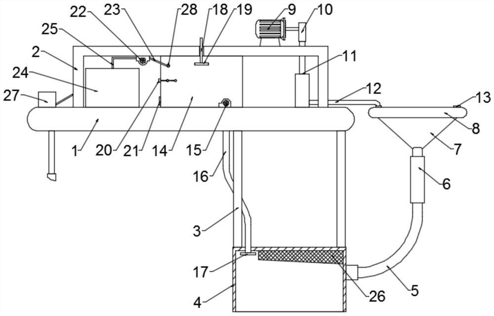
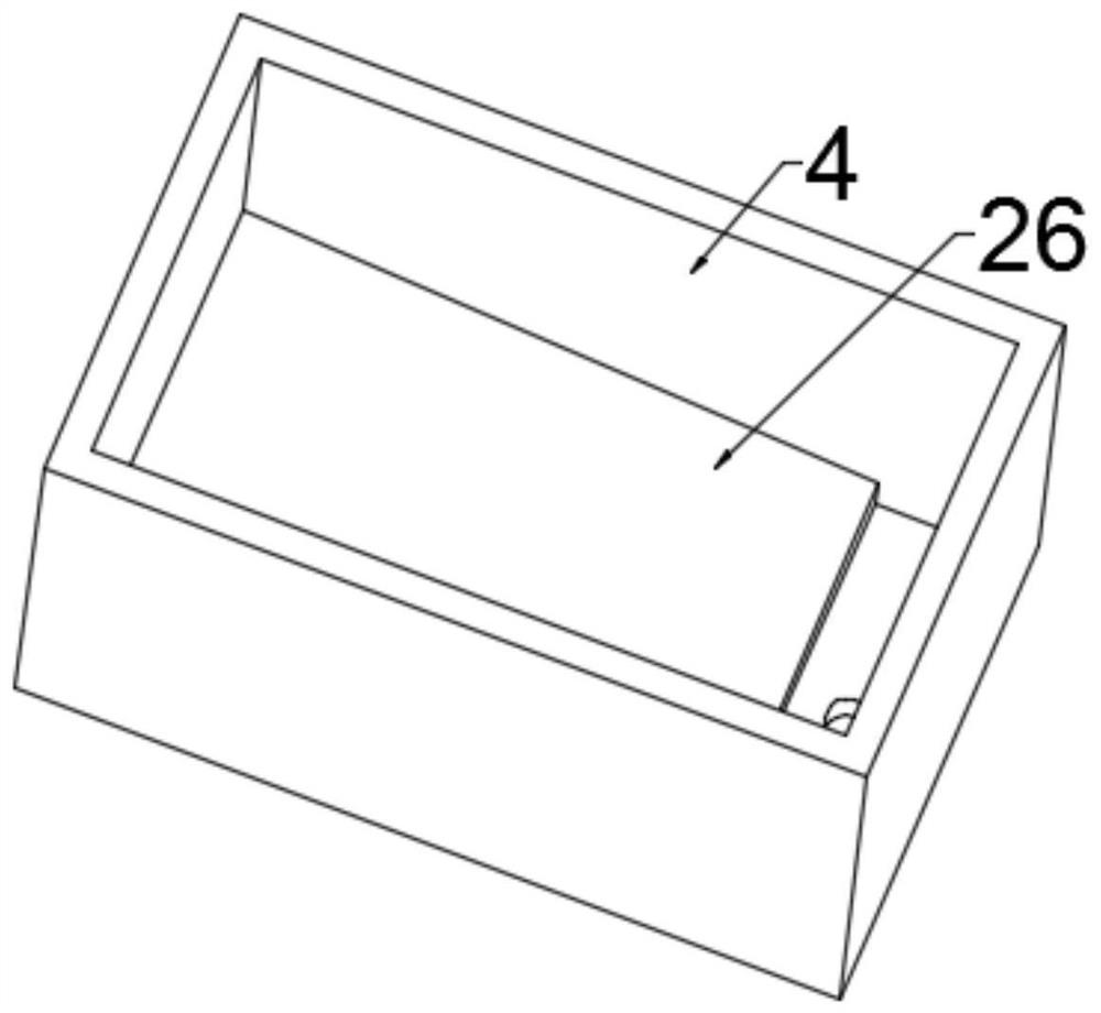
[0022] Example 1: Please refer to Figure 1-3 , a marine oil recovery device, comprising a horizontal floating plate 1, an installation frame 2 is fixedly connected above the horizontal floating plate 1, a connecting column 3 is fixedly connected to the right side below the horizontal floating plate 1, and a cover body 4 is fixedly connected to the bottom of the connecting column 3 The right side of the cover body 4 is fixedly connected with an arc-shaped connecting pipe 5, the end of the arc-shaped connecting pipe 5 is fixedly connected with a guide sleeve 6, the inner side of the guide sleeve 6 is slidingly connected with an oil collecting funnel 7, and the outer side of the oil collecting funnel 7 is fixedly connected with a An annular airbag 8 is fixedly connected with a motor 9 at the top of the installation frame 2, and a cam 10 is fixedly connected at the output end of the motor 9, and an inflator 11 is fixedly connected with the upper right side of the horizontal floati...

Embodiment 2

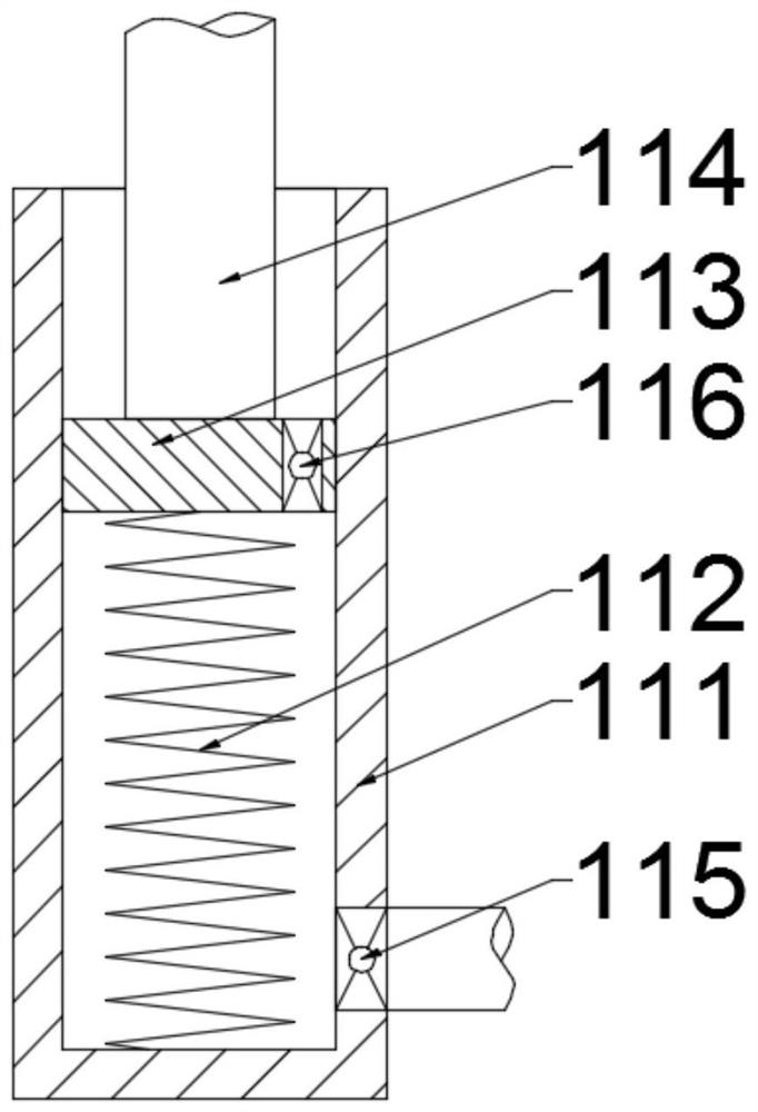
[0036] Embodiment 2: This embodiment provides a specific inflatable device structure as a further supplementary improvement to the previous embodiment: the inflatable device 11 includes an inflatable sleeve 111, and the inner side of the inflatable sleeve 111 is fixedly connected with an inflatable slide 113 through a spring 112 , the inflatable slide plate 113 is slidably connected with the inflatable sleeve 111, a pressure column 114 is fixedly connected above the inflatable slide plate 113, and the pressure column 114 resists the cam 10 under the force of the spring 112, and the first pipeline 12 is fixedly connected with an air outlet The one-way valve 115 is fixedly connected with the air intake one-way valve 116 on the inflatable slide plate 113 .

[0037]The working principle of the present invention is: when in use, the device is placed in the area where the oil leaks, and after the motor 9 is turned on, the motor rotates and drives the cam 10 to move and inflate the in...


PUM


Abstract

The invention discloses a marine oil pollution recovery device, and relates to an oil pollution recovery device. The marine oil pollution recovery device comprises a horizontal floating plate, whereinan upper part of the horizontal floating plate is fixedly connected with an installation frame, a right side below the horizontal floating plate is fixedly connected with a connecting column, a bottom of the connecting column is fixedly connected with a cover body, a right side of the cover body is fixedly connected with an arc-shaped connecting pipe, a tail end of the arc-shaped connecting pipeis fixedly connected with a guide sleeve, an inner side of the guide sleeve is slidingly connected with an oil collecting funnel, an the outer side of the oil collecting funnel is fixedly connected with an annular airbag, a top of the installation frame is fixedly connected with a motor, an output end of the motor is fixedly connected with a cam, a right side above the horizontal floating plate isfixedly connected with an inflator, and the inflator is matched with the cam. When using, oil can be separated from seawater completely for twice, so the oil pollution floating on the surface of thesea can be recovered, the separation effect is good, the oil pollution can be separated well, the seawater is avoided being polluted seriously, and adequate protection is provided to the leakage of marine oil pollution.

Description

technical field [0001] The invention relates to an oil pollution recovery device, in particular to a marine oil pollution recovery device. Background technique [0002] As an important energy source, deep-sea oil has high economic efficiency due to its huge reserves. However, once the crude oil leaks, it will cause huge losses, including direct economic losses and environmental pollution. Take the 2010 U.S. Gulf of Mexico crude oil spill as an example, oil continued to flow out from the sea; natural oil easily fused with seawater; the resulting viscous mixture was difficult to burn and even difficult to clean up; Difficult to clean swamps. [0003] Some existing offshore oil pollution recovery devices use oil-absorbing felt to absorb oil. Although it is a more feasible solution, after all, the capacity of oil-absorbing felt is limited, and the oil-absorbing efficiency is limited. Too much seawater leads to low efficiency of oil removal, and requires secondary separation o...

Claims


Application Information

Patent Timeline
Patent Type & Authority Applications(China)
IPC IPC(8): E02B15/10
CPCE02B15/10E02B15/106Y02A20/204
Inventor 朱宇新赵俊杰赵英杰乔建哲董世培焦润红
Owner TIANJIN RES INST FOR WATER TRANSPORT ENG M O T
Learn More