Foundation pit inclined strut device and construction method

A technology of diagonal braces and foundation pits, which is applied in infrastructure engineering, excavation, sheet pile walls, etc., can solve the problems of resource material waste, difficult disassembly, long construction period, etc., and achieve the effect of increasing friction and facilitating recycling

Inactive Publication Date: 2020-11-06
王军霞
View PDF0 Cites 4 Cited by
  • Summary
  • Abstract
  • Description
  • Claims
  • Application Information

AI Technical Summary

Problems solved by technology

[0003] At present, the diagonal braces supported in building buildings, subway stations and tunnel foundation pits are mostly cast-in-place reinforced concrete structures. Because cast-in-place reinforced concrete needs to be poured and maintained on site, the construction period is very long, and it is difficult to disassemble due to the use of cement pouring. The received diagonal bracing device cannot be recycled again, resulting in a huge waste of resources and materials, and the remaining cement piles also need to be processed

Method used


Image

  • Foundation pit inclined strut device and construction method
  • Foundation pit inclined strut device and construction method
  • Foundation pit inclined strut device and construction method

Examples


Embodiment 1

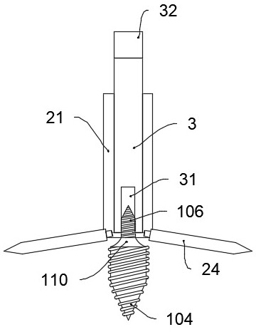
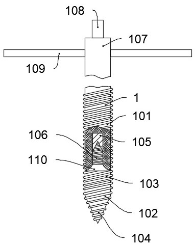
[0037] Such as Figure 1-7 As shown, a foundation pit brace device includes an embedded assembly 1, the embedded assembly 1 includes an upper embedded rod 101 and a lower fixing head 102, the lower end of the upper embedded rod 101 is provided with a first screw hole 105, the lower fixing head 102 and the upper The surface of the embedding rod 101 is provided with a helical pattern 103, through the helical thread 103, when the embedding component 1 rotates into the ground, the surrounding soil is conveyed out by a screw, which is convenient for the embedding component 1 to go deep. The friction between the lower fixed head 102 and the soil effectively prevents the lower fixed head 102 from breaking away from the soil. The upper end of the lower fixed head 102 is fixedly connected with a base 110, and the base 110 can move with the movement of the lower fixed head 102. The upper end of base 110 is fixedly connected with screw rod 106, and screw rod 106 can move with the movemen...

Embodiment 2

[0043] Such as Figure 8 As shown, the difference between this embodiment and Embodiment 1 is that the cross-section of the side of the positioning leg 24 away from the central shaft of the positioning cylinder 2 is tapered, and when the positioning leg 24 rotates around the ring block 23, The surrounding soil can be squeezed, and the soil resistance that the positioning leg 24 is subjected to when rotating can be reduced by setting the taper.

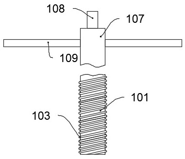
[0044] Thread the embedded rod 101 and the lower fixed head 102 and fasten them, select a suitable position on the soft surface soil surface, rotate the upper embedded rod 101 and the lower fixed head 102 by turning the handle 109 and press them into the soil, and the soil is The spiral pattern 103 is rotated and discharged, and the upper embedded rod 101 and the lower fixing head 102 gradually go deep underground to form the preliminary positioning and fixing of the lower fixing head 102;

[0045] The preliminarily fixed upper embedd...


PUM


Abstract

The invention belongs to the technical field of building construction, and particularly relates to a foundation pit inclined strut device and a construction method. The foundation pit inclined strut device comprises an embedding assembly, the embedding assembly comprises an upper embedding rod and a lower fixing head, a first screw hole is formed in the lower end of the upper embedding rod, and threads are arranged on the surfaces of the lower fixing head and the upper embedding rod; the upper end of the lower fixing head is fixedly connected with a base, the upper end of the base is fixedly connected with a screw rod, the screw rod is in threaded connection with the interior of the first screw hole, and the lower fixing head is cooperatively used with a connecting rod; and a third screw hole is formed inside the connecting rod, the connecting rod is in threaded connection with the interior of the positioning cylinder, the lower end of the positioning cylinder is fixedly connected witha connecting circular ring, the connecting circular ring is sleeved with a plurality of ring blocks, the lower ends of the ring blocks are fixedly connected with positioning supporting legs. According to the foundation pit inclined strut device and the construction method, a foundation pit stroke carrying device can be rapidly unfolded, fixed and recycled for secondary use.

Description

technical field [0001] The invention belongs to the technical field of building construction, and in particular relates to a foundation pit diagonal bracing device and a construction method. Background technique [0002] The foundation pit support is to ensure the safety of the underground structure construction and the surrounding environment of the foundation pit, and the support, reinforcement and protection measures adopted for the side wall of the foundation pit and the surrounding environment. Diagonal bracing is also known as diagonal throwing brace or throwing support, and the angle between the diagonal brace and the bottom of the foundation pit should not be greater than 25 degrees in general. The horizontal projection length of the diagonal brace should not be greater than the excavation depth of the foundation pit. [0003] At present, the diagonal braces supported in building buildings, subway stations and tunnel foundation pits are mostly cast-in-place reinforc...

Claims


Application Information

Patent Timeline
Patent Type & Authority Applications(China)
IPC IPC(8): E02D17/04E02D5/80
CPCE02D5/80E02D5/801E02D17/04E02D2600/30
Inventor 王军霞
Owner 王军霞
Why Eureka
Try Eureka