A long tile auxiliary laying equipment for brick wall construction

A ceramic tile and brick wall technology, applied in the field of auxiliary laying equipment for long tiles used in brick wall construction, can solve problems such as low efficiency and cumbersome steps, and achieve the effects of avoiding resource waste, saving time, and improving work efficiency

Active Publication Date: 2021-12-17
深圳市红头船建设集团有限公司
View PDF5 Cites 0 Cited by
  • Summary
  • Abstract
  • Description
  • Claims
  • Application Information

AI Technical Summary

Problems solved by technology

[0004] In order to overcome the current disadvantages of manual shoveling of cement and manual lifting of tiles for turning over, cumbersome steps and low efficiency, the technical problem of the present invention is to provide a method that can automatically lift and unload cement without manual lifting of tiles. Auxiliary laying equipment for long tiles for brick wall construction by turning over, simplifying steps and improving efficiency

Method used


Image

  • A long tile auxiliary laying equipment for brick wall construction
  • A long tile auxiliary laying equipment for brick wall construction
  • A long tile auxiliary laying equipment for brick wall construction

Examples


Embodiment 1

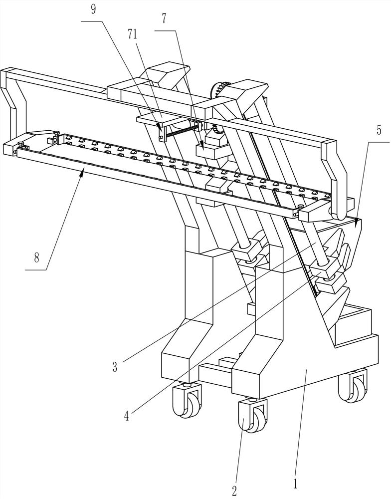
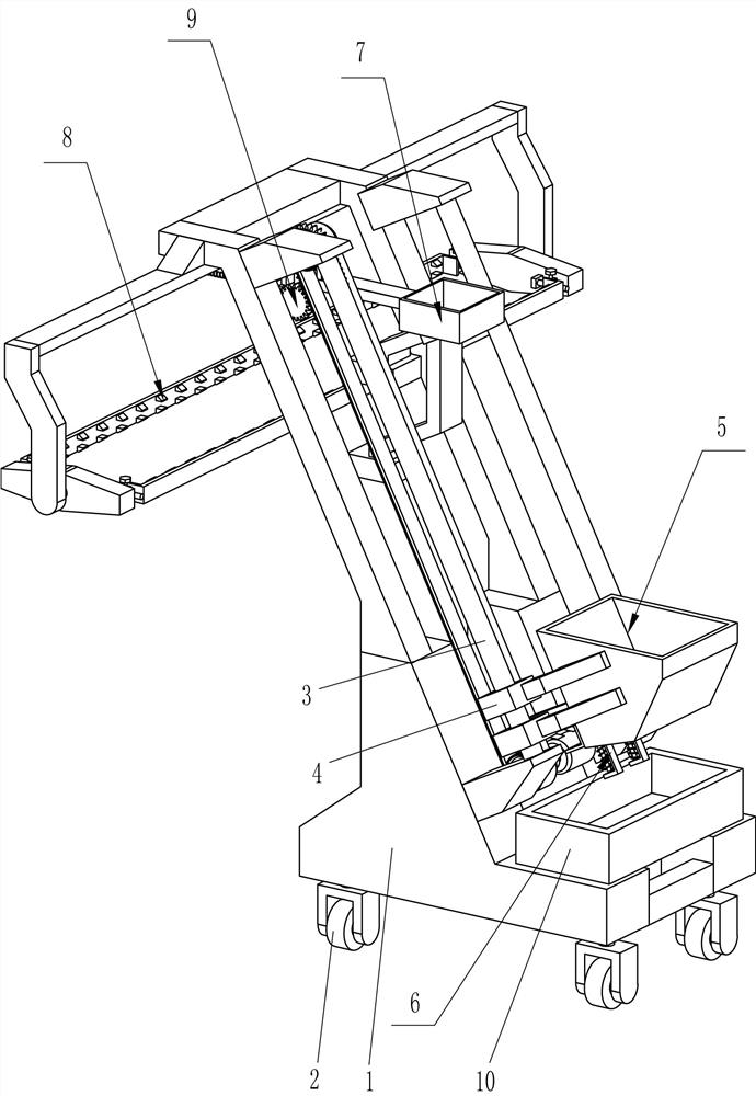
[0032] A long tile auxiliary laying equipment for brick wall construction, such as Figure 1-4 As shown, it includes a mounting frame 1, a universal wheel 2, a first guide rail 3, a first guide sleeve 4, a feeding device 5, a cover opening device 6, a feeding device 7 and a placement device 8, specifically:

[0033] Four sets of universal wheels 2 are connected to the lower side of the installation frame 1, and two sets of first guide rails 3 are connected to the upper side of the installation frame 1. The first guide rails 3 are slidably connected to the first guide sleeve 4, and the first guide sleeve 4 There is a feeding device 5 between them, the lower left side of the feeding device 5 is provided with a cover opening device 6, and the upper left side of the mounting frame 1 is provided with a blanking device 7, the cover opening device 6 can be in contact with the blanking device 7, and the mounting frame 1 The left side is provided with placing device 8.

[0034] When i...

Embodiment 2

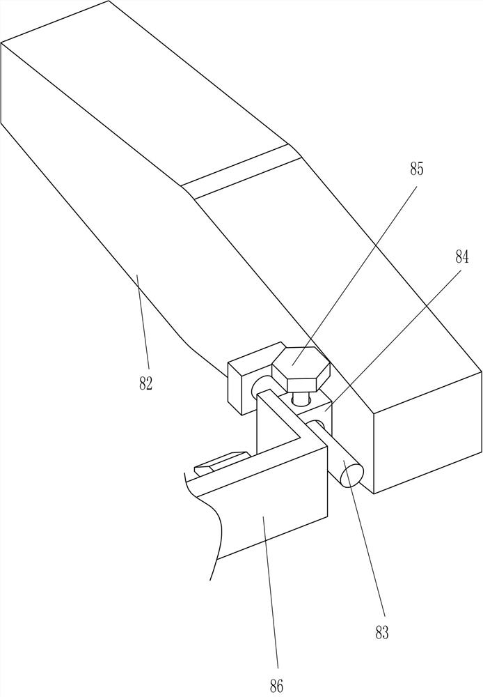
[0036] On the basis of Example 1, such as Figure 5-12 As shown, the feeding device 5 includes a placement bucket 51, a first rotating shaft 52, a belt transmission assembly 53, a moving block 54 and a servo motor 55, specifically:

[0037] A placement bucket 51 is connected between the first guide sleeves 4. The placement bucket 51 is a structure with an opening on the left side. The cover opening device 6 is located on the lower side of the placement bucket 51. The upper left side and the lower right side of the front part of the mounting frame 1 are connected in a rotational manner. There is a first rotating shaft 52, a belt transmission assembly 53 is connected between the first rotating shafts 52, a moving block 54 is connected to the upper side of the belt driving assembly 53, the moving block 54 is connected to the lower side of the placement bucket 51, and a servo is connected to the lower side of the mounting frame 1. The motor 55 and the servo motor 55 are connected ...


PUM


Abstract

The invention relates to a decoration equipment, in particular to an auxiliary long ceramic tile laying equipment for brick wall construction. The technical problem of the present invention is to provide an auxiliary laying equipment for long tiles for brick wall construction that can automatically lift and unload cement, does not need to manually pick up the tiles for flipping, and simplifies steps to improve efficiency. The technical embodiment of the present invention is: a long ceramic tile auxiliary laying equipment for brick wall construction, including a mounting frame, and multiple sets of universal wheels are arranged on one side of the mounting frame; At the position on one side of the universal wheel, and the first guide rail is provided with a first guide sleeve; a feeding device. The present invention lifts the cement by using the placing bucket, and through the opening and closing of the baffle plate through the temporary storage bucket, the cement can be lifted to the tiles and brick walls without manual shoveling, avoiding frequent bending, and the cement can also be transported It will not be damaged, avoiding the waste of resources.

Description

technical field [0001] The invention relates to a decoration equipment, in particular to an auxiliary long ceramic tile laying equipment for brick wall construction. Background technique [0002] At present, when laying long tiles on the side of a brick wall, it is necessary to manually place the long tiles on the brick wall with the bottom of the tiles facing up, and then manually hold the cement shovel to scoop up the barreled cement on the bottom to the tiles and the brick wall On the other hand, this needs to be done manually many times, and frequent bending is required, which is very time-consuming and labor-intensive, and it is necessary to pour cement on brick walls and tiles step by step, resulting in cumbersome procedures, and after the cement pouring is completed, manual work is required. Pick up the long tiles and turn and turn them over so that the side of the tiles with cement covers the brick wall, which can easily break the tiles, and the cement is also easy t...

Claims


Application Information

Patent Timeline
Patent Type & Authority Patents(China)
IPC IPC(8): E04F21/18E04F21/02
CPCE04F21/1838E04F21/1844E04F21/023
Inventor 钟明有
Owner 深圳市红头船建设集团有限公司
Why Eureka
Try Eureka