Low-water-suction water pump

A low water absorption, water pump technology, applied in the direction of pumps, pump components, rotary piston pumps, etc., can solve the problems of unstable pumping state and pump body damage, and achieve enhanced water delivery efficiency, accelerated flow efficiency, and avoided water flow interruption. Effect

Active Publication Date: 2020-11-06
LVMEI PUMP CO LTD
View PDF6 Cites 1 Cited by
  • Summary
  • Abstract
  • Description
  • Claims
  • Application Information

AI Technical Summary

Problems solved by technology

[0005] In order to make up for the deficiencies of the prior art and solve the problem in the prior art that when the water pump is operating at a low water level, due to the presence of more air in the water inlet pipe, the pumping state of the water pump is unstable, thereby causing damage to the pump body, the present invention A Low Suction Pump

Method used


Image

  • Low-water-suction water pump
  • Low-water-suction water pump
  • Low-water-suction water pump

Examples


Embodiment approach

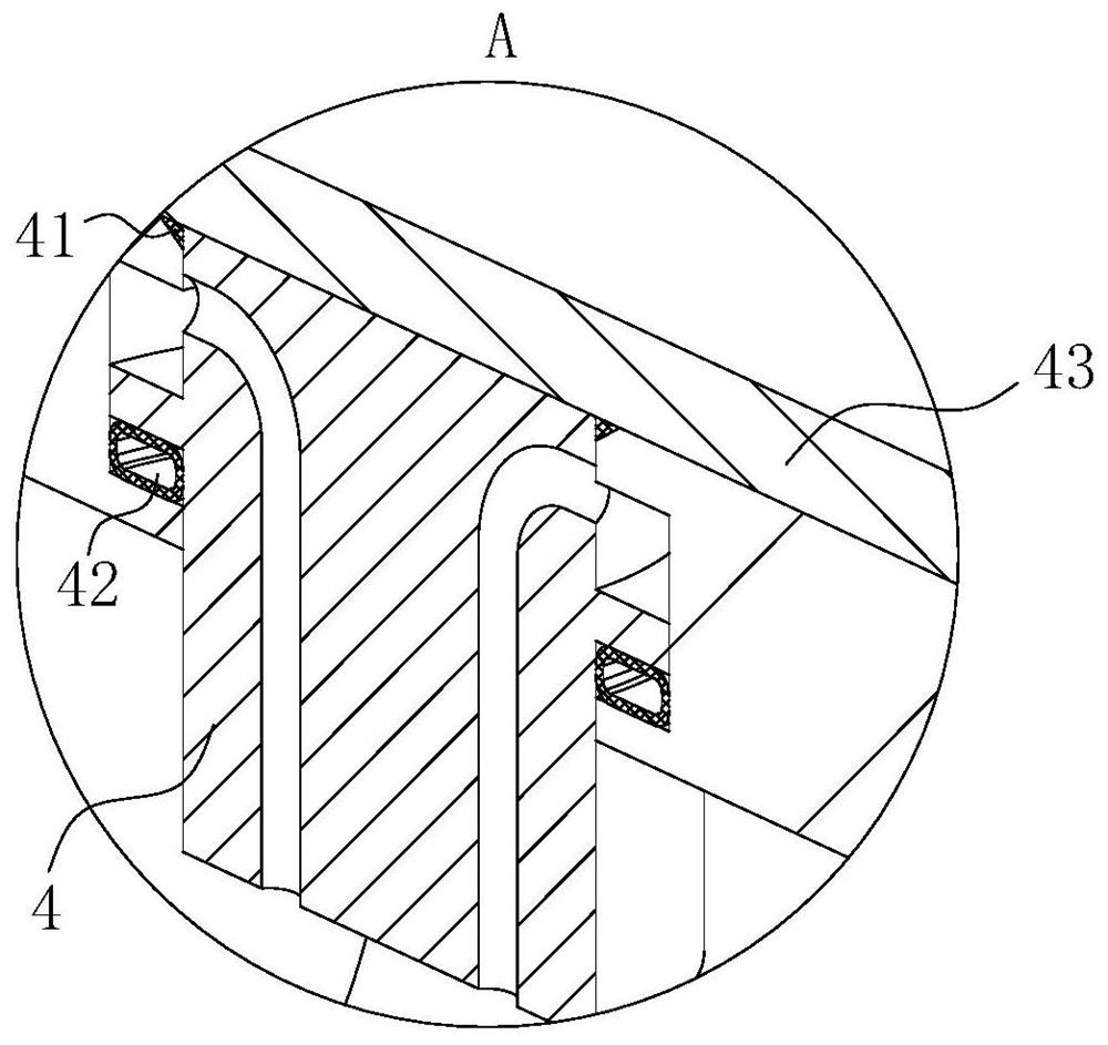
[0025] As an embodiment of the present invention, a sliding groove is provided on the side of the water inlet tank close to the booster chamber; the sliding groove is designed in a "ten" shape; a buoy 4 is slidably connected in the sliding groove; the buoy 4 runs through The sliding groove extends into the water inlet tank; the buoy 4 is provided with a first through hole; the first through hole is designed in an inverted "L" shape; the buoy 4 is made of light water buoyant material; the buoy 4 A sealing ring 41 is fixedly connected to the side wall of the end far away from the water inlet tank; in the initial state, the buoy 4 seals the sliding groove under the action of gravity; during operation, the buoy 4 seals the sliding groove in the initial state, and as the water flow continues to be drawn, the water flow finally Entering the water inlet tank, as the water flows into the booster chamber, it rotates rapidly under the action of the booster wheel 3, thereby increasing the...


PUM


Abstract

The invention belongs to the technical field of water pumping equipment, and particularly discloses a low-water-suction water pump which comprises a base, a pump body and a motor. The pump body is fixedly connected to the upper surface of the base. The pump body is of a cylindrical design. A pressurizing cavity and a self-sucking cavity are formed in the pump body. A supporting plate is fixedly connected with the side, away from the base, of the pump body. A supporting column is fixedly connected to the base. The supporting column is fixedly connected with the supporting plate. The motor is fixedly connected to the side, away from the pump body, of the supporting plate through a flange. A rotary shaft is rotationally connected into the pressurizing cavity. By arranging a first rotating wheel, a second rotating wheel and a piston column, by means of the sealing effect between the first rotating wheel and the second rotating wheel and the self-sucking cavity, air in a water pumping pipeis continuously sucked upwards, then water flow rises up under the action of pressure and finally enters the self-sucking cavity through a water inlet groove, and meanwhile a piston rod does reciprocating motions to enhance the sucking effect of the first rotating wheel and the second rotating wheel in the self-sucking cavity.

Description

technical field [0001] The invention belongs to the technical field of water pumping equipment, in particular to a low-suction water pump. Background technique [0002] In the prior art, there is a certain height difference between the pump inlet pipe and the liquid surface when performing low-water pumping operations, so there is a large amount of air in the pumping pipes. When performing pumping operations, most of the existing water pumps are equipped with vacuum pumps, etc. Equipped with waterless vacuum pumping equipment to realize the self-absorption effect of the water pump, but when the water level is low, the vacuum degree in the pump body is unstable, which is likely to cause intermittent water flow, which in turn makes the water output of the pump unstable. On the one hand, the intermittent water pumping efficiency is low , At the same time, Hairongyi has a certain negative impact on the pump body, resulting in a reduction in the service life of the pump. [0003...

Claims


Application Information

Patent Timeline
Patent Type & Authority Applications(China)
IPC IPC(8): F04C2/12F04C15/06F04C11/00
CPCF04C2/126F04C15/06F04C11/00
Inventor 陈平
Owner LVMEI PUMP CO LTD
Why Eureka
Try Eureka