Biomass power generation system

A biomass power generation and component technology, which is applied in the direction of biofuel, steam generation, machine/engine, etc., can solve the problems that the capacity of the furnace cannot be adjusted, and the heat of biomass combustion cannot be fully utilized.

Inactive Publication Date: 2020-11-06
高继慧
View PDF1 Cites 0 Cited by
  • Summary
  • Abstract
  • Description
  • Claims
  • Application Information

AI Technical Summary

Problems solved by technology

However, the device cannot adjust the capacity of the furnace and cannot fully utilize the heat generated by biomass combustion

Method used


Image

  • Biomass power generation system
  • Biomass power generation system
  • Biomass power generation system

Examples


specific Embodiment approach 1

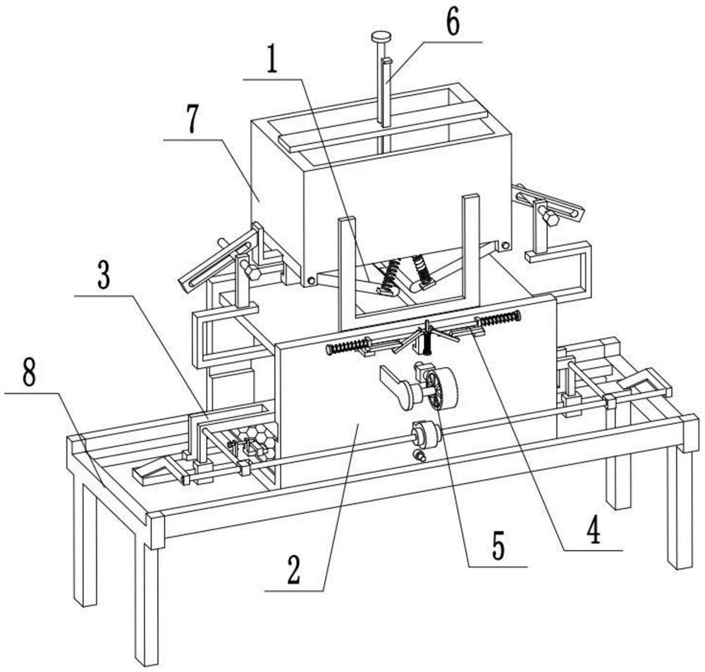
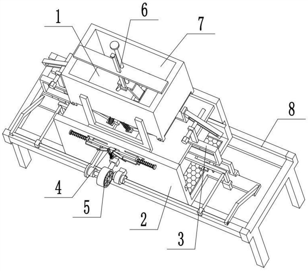
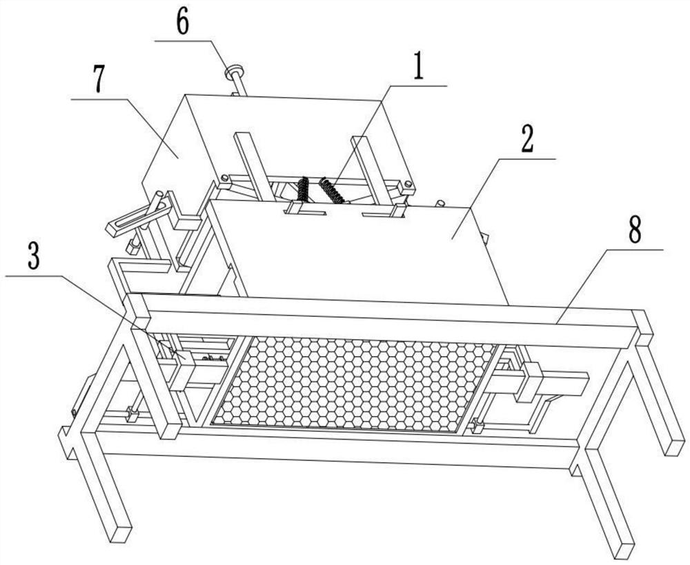
[0030] Combine below Figure 1-10Describe this embodiment, a biomass power generation system, including a discharge assembly 1, a combustion furnace assembly 2, an adjustable furnace wall assembly 3, an upper baffle assembly 4, a power conversion device 5, a push plate 6, and a feed box 7 And underframe 8, described discharge assembly 1 is provided with two, and two discharge assemblies 1 are symmetrically arranged on the lower end of feeding box 7, and feeding box 7 is fixedly connected on the combustion furnace assembly 2 by U-shaped plate, The combustion furnace assembly 2 is fixedly connected to the bottom frame 8, and the adjustable furnace wall assembly 3 is connected to the combustion furnace assembly 2. The two ends of the adjustable furnace wall assembly 3 are respectively connected with the two discharge assemblies 1, and the upper baffle The assembly 4 is arranged on the upper end of the combustion furnace assembly 2 , the power conversion device 5 is arranged on th...

specific Embodiment approach 2

[0032] Combine below Figure 1-10 To illustrate this embodiment, the discharge assembly 1 includes a lower baffle 1-1, a long shaft 1-2, an L-shaped connecting rod 1-3, a grooved rod 1-4, a spring seat 1-5 and a first spring 1 -6; the lower baffle plate 1-1 is fixedly connected to the long shaft 1-2, the long shaft 1-2 is rotatably connected to one side of the lower end of the feed box 7, and the outer end of the long shaft 1-2 is fixedly connected to the L-shaped connecting rod 1-3, the groove rod 1-4 is fixedly connected to the L-shaped connecting rod 1-3, and the adjustable furnace wall assembly 3 is connected with the groove rod 1-4; the inner end of the lower baffle 1-1 is fixedly connected symmetrically Two spring seats 1-5 are respectively fixedly connected with a first spring 1-6, and the two first springs 1-6 are fixedly connected to the bottom surface of the feeding box 7. In use, when the adjustable furnace wall assembly 3 is adjusted to change the furnace space, t...

specific Embodiment approach 3

[0034] Combine below Figure 1-10 To illustrate this embodiment, the combustion furnace assembly 2 includes a bottom frame 2-1, a side fixed wall 2-2, an upper through groove 2-3, an inner chute 2-4, an ignition device 2-5, and a side sliding rod 2 -6. Barrel 2-7 and fire grate 2-8; the bottom frame 2-1 is fixedly connected to the bottom frame 8, and the two ends of the bottom frame 2-1 are respectively fixedly connected to a side fixed wall 2-2, two side The upper end of the fixed wall 2-2 is respectively provided with one or two upper through grooves 2-3, and the middle part of the inner wall of the two side fixed walls 2-2 is respectively provided with two inner chute 2-4, and the side fixed wall 2-2 of the front end The lower end of the bottom frame is provided with an ignition device 2-5, and the power generation conversion device 5 is located at the upper end of the fixed wall 2-2 on the front end side, and the power generation conversion device 5 is located at the lower...


PUM


Abstract

The invention discloses a biomass power generation system, and relates to the field of biomass power generation equipment. The biomass power generation system comprises discharging assemblies, a combustion furnace assembly, an adjustable furnace wall assembly, an upper baffle assembly, a power generation conversion device, a plate pushing piece, a feeding box and a bottom frame, and has the beneficial effects that the capacity of a smelting furnace can be adjusted, the feeding amount is synchronously adjusted according to the capacity of the smelting furnace, heat generated by biomass combustion is fully utilized, the number of the discharging assemblies is two, the two discharging assemblies are symmetrically arranged at the lower end of the feeding box, the feeding box is fixedly connected to the combustion furnace assembly through a U-shaped plate, the combustion furnace assembly is fixedly connected to the bottom frame, the adjustable furnace wall assembly is connected to the combustion furnace assembly in a matching mode, the two ends of the adjustable furnace wall assembly are connected with the two discharging assemblies in a matching mode correspondingly, the upper baffle assembly is arranged at the upper end of the combustion furnace assembly, the power generation conversion device is arranged at the front end of the combustion furnace assembly, and the plate pushing piece is arranged on the feeding box.

Description

technical field [0001] The invention relates to the field of biomass power generation equipment, in particular to a biomass power generation system. Background technique [0002] The existing patent number is CN201910630535.X, a biomass power generation device that facilitates ash removal and ash discharge. The invention discloses a biomass power generation device that is convenient for ash removal and ash discharge, including a boiler and a steam turbine generator set; The feature is that the boiler includes a boiler body, a furnace is arranged in the boiler body, and a rotating scraper is arranged in the furnace. The invention is provided with a motor-driven scraper in the furnace to rotate and clean the inner wall of the furnace after combustion, avoiding coking, prolonging the service life of the boiler, ensuring sufficient combustion, and reducing exhaust emissions; The ash on the grate is cleaned, and the ash is efficiently cleaned through the ash cleaning plate and t...

Claims


Application Information

Patent Timeline
Patent Type & Authority Applications(China)
IPC IPC(8): F23B40/00F23M5/00F22B31/00F01K11/02F01D15/10
CPCF01D15/10F01K11/02F22B31/00F23B40/00F23M5/00Y02E50/10
Inventor 高继慧
Owner 高继慧
Why Eureka
Try Eureka